
User Manual


PNOZ 11
Operating Manual PNOZ 11
19147-EN-05
27
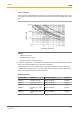
Service life graph
The service life graphs indicate the number of cycles from which failures due to wear must
be expected. The wear is mainly caused by the electrical load; the mechanical load is negli-
gible.
Cycles x 1000
Switching current (A)
Example
} Inductive load: 0.2 A
} Utilisation category: AC15
} Contact service life: 4 000 000 cycles
Provided the application to be implemented requires fewer than 4 000 000 cycles, the PFH
value (see Technical details) can be used in the calculation.
To increase the service life, sufficient spark suppression must be provided on all output
contacts. With capacitive loads, any power surges that occur must be noted. With DC con-
tactors, use flywheel diodes for spark suppression.
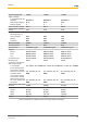
Order reference
Product type Features Connection type Order No.
PNOZ 11 24 VDC, 24 VAC Screw terminals 774 080
PNOZ 11 24 VDC, 42 VAC Screw terminals 774 081
PNOZ 11 24 VDC, 48 VAC Screw terminals 774 082
PNOZ 11 24 VDC, 110 - 120
VAC
Screw terminals 774 085
PNOZ 11 24 VDC, 230 - 240
VAC
Screw terminals 774 086