
User Manual


PNOZ 11
Operating Manual PNOZ 11
19147-EN-05
10
Wiring
Please note:
} Information given in the "Technical details [ 15]" must be followed.
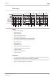
} Delivery status of units with screw terminals: Link between S11-S12 (dual-channel input
circuit) and link between Y1-Y2 (feedback loop)
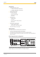
} Outputs 13-14, 23-24, 33-34, 43-44, 53-54, 63-64, 73-74 are safety contacts; output
81-82 is an auxiliary contact (e.g. for display).
} Auxiliary contact 81-82 shouldnot be used for safety circuits!
} To prevent contact welding, a fuse should be connected before the output contacts (see
Technical details [ 15]).
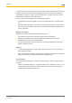
} Calculation of the max. cable runs l
max
in the input circuit:
R
lmax
R
l
/ km
I
max
=
R
lmax
= max. overall cable resistance (see Technical details [ 15])
R
l
/km = cable resistance/km
} Use copper wire that can withstand 60/75°C.
} Do not switch low currents using contacts that have been used previously with high cur-
rents.
} Sufficient fuse protection must be provided on all output contacts with capacitive and in-
ductive loads.
} When connecting magnetically operated, reed proximity switches, ensure that the max.
peak inrush current (on the input circuit) does not overload the proximity switch.
} With a 24 VDC supply voltage via terminals B1, B2, the power supply must comply with
the regulations for extra low voltages with safe electrical separation (SELV, PELV) in
accordance with VDE 0100, Part 410.
} Ensure the wiring and EMC requirements of IEC 60204-1 are met.
Important for detection of shorts across contacts:
As this function for detecting shorts across contacts is not failsafe, it is tested by Pilz during
the final control check. If there is a danger of exceeding the cable length, we recommend
the following test once the unit is installed:
1. Unit ready for operation (output contacts closed)
2. Short circuit the test terminals S22, S32 for detecting shorts across the inputs.
3. The unit‘s fuse must be triggered and the output contacts must open. Cable lengths in
the scale of the maximum length can delay the fuse triggering for up to 2 minutes.
4. Reset the fuse: Remove the short circuit and switch off the supply voltage for approx. 1
minute.