
Datasheet


PicoScope 3000 Series
Advanced digital triggers
Since 1991 Pico Technology have been pioneering the use of digital triggering
and precision hysteresis using the actual digitized data. Traditionally digital
oscilloscopes have used an analog trigger architecture based on comparators,
which can cause time and amplitude errors that cannot always be calibrated out.
Additionally, the use of comparators can often limit the trigger sensitivity at high
bandwidths and can create a long trigger rearm delay.
PicoScopes broke new ground by being the first to use digital triggering. This
method reduces errors and allows our oscilloscopes to trigger on the smallest
signals, even at the full bandwidth. Trigger levels and hysteresis can be set with
high precision and resolution.
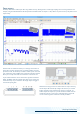
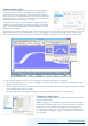
Digital triggering also reduces rearm delay and this, combined with the segmented memory, allows the triggering and capture of events that
happen in rapid sequence. At the fastest timebase you can use rapid triggering to collect 10 000 waveforms in under 6 milliseconds. The
mask limit testing function can then scan through these waveforms to highlight any failed waveforms for viewing in the waveform buffer.
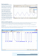
As well as simple edge triggers, a selection of time-based triggers are available for both digital and analog inputs.
• The pulse-width trigger allows you to trigger on either high or low pulses, which are shorter or longer than a specified time, or which
fall inside or outside a range of times.
• The interval trigger measures the time between subsequent rising or falling edges. This allows you to trigger if a clock signal falls outside
of an acceptable frequency range, for example.
• The dropout trigger fires when a signal stops toggling for a defined interval of time, functioning as a watchdog timer.
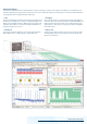
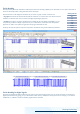
Triggering for digital inputs
The PicoScope 3000 Series MSO models offer a comprehensive set of advanced
triggers for digital channels.
With logic triggering you can trigger the scope when any or all of the 16 digital
inputs match a user-defined pattern. You can specify a condition for each channel
individually, or set up a pattern for all channels at once using a hexadecimal or
binary value. You can also combine logic triggering with an edge trigger on any
one of the digital or analog inputs, to trigger on data values in a clocked parallel
bus for example.