
User Manual


ADC-20/ADC-24 Terminal Board User Guide Pico Technology
4 DO117-5
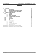
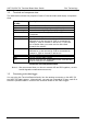
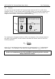
2.1.3 Voltage divider connection
For voltages beyond -2.5 V to +2.5 V, use a voltage divider connection.
The voltage that the ADC sees, V
ADC
, depends on V
IN
and the values of R
A
and R
B
, and
is given by the following equation:
BA
B
INADC
RR
R
VV
+
×=
Choose values of R
A
and R
B
so that V
ADC
is approximately +2.5 V when V
IN
is at its
highest.
To minimise errors in the measured voltage, V
ADC
, caused by loading of the source
voltage V
IN
, ensure that the combined resistance of R
A
+ R
B
is much greater than the
resistance of the voltage source. If you are unsure of the resistance of the voltage
source, use large values for R
A
and R
B
such that R
A
+ R
B
is about 10 kΩ.
If you have chosen a value for R
B
that is greater than 10 kΩ, and you need high
accuracy, then you will need to take into account the ADC’s input resistance R
ADC
,
which acts in parallel with R
B
. Use the following equation to obtain a value for the
parallel equivalent resistance of R
B
and R
ADC
, R
BEQ
, then use R
BEQ
instead of R
B
in the
previous equation:
ADCB
ADCB
BEQ
RR
RR
R
+
×
=
where R
ADC
= 1 MΩ.
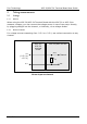
R
A
R
B
R
ADC
AG
0 V
V
IN
V
ADC
ADC
-
20/
ADC
-
24
unit
ADC-20/ADC-24
terminal
board
Voltage divider
Channel