
User Manual


ADC-20/ADC-24 Terminal Board User Guide Pico Technology
2 DO117-5
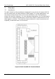
1.2 Terminals and component sites
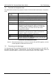
The table below shows the purpose of each of the terminals and empty component
sites.
Terminal
or site
Description
1 to 16 Connections to ADC channels 1 to 16.
AG Connections to analogue ground. (Note 1)
DG Connections to digital ground. (Note 1)
+5 V and -5 V Low-current power supply (up to 2 mA) for sensors,
if required.
+2.5 V Reference voltage.
R1a to R16a Sites for series resistors in voltage dividers.
Referred to in the text as R
A
. R1a is connected to
channel 1, R2a to channel 2 and so on. If you use
one of these sites, you must cut the thin track
beneath the resistor.
R1b to R16b Sites for shunt resistors in voltage dividers.
Referred to in the text as R
B
. R1b is connected to
channel 1, R2b to channel 2 and so on.
Q1 Site for LM35 temperature sensor.
BNC Site for upright BNC socket.
IC1 Site for a 14-pin DIL integrated circuit. You can use
wires to link pins to channels.
Terminals and component sites
Note 1: We recommend that you do not connect AG and DG together, as this
would degrade measurement accuracy.
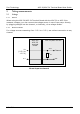
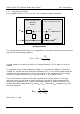
1.3 Connecting to the data logger
You can plug the Terminal Board directly into the analog connector on the ADC-20
and ADC-24 Data Loggers. Alternatively, you can use a standard 25-way male-D to
female-D parallel cable to connect the Terminal Board to the Data Logger.