
User Manual


PicoScope 5000D Series Flexible Resolution Oscilloscopes User's Guide 9
Copyright © 2018 Pico Technology Ltd. All rights reserved. ps5000d.en r1
3 Product information
3.1 Maximum sampling rate
For full specifications and further information, refer to the PicoScope 5000 Series page on our website or to the
PicoScope 5000D Series data sheet, available on our website.
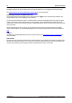
How maximum sampling rate varies by resolution and the number of channels in use
Resolution
Maximum sampling rate with number of channels* in use
Any 1 channel
Any 2 channels
3 or 4 channels
More than 4 channels
8-bit
1 GS/s
500 MS/s
250 MS/s
125 MS/s
12-bit
500 MS/s
250 MS/s
125 MS/s
62.5 MS/s
14-bit
125 MS/s
125 MS/s
125 MS/s
62.5 MS/s
15-bit
**125 MS/s
**125 MS/s
**125 MS/s
-
16-bit
***62.5 MS/s
***62.5 MS/s
***62.5 MS/s
-
*Channels refers to the number of analog channels and digital ports. There are two digital ports on the MSO
models: the first port includes any number of connections to the D0-D7 inputs, the second includes any number
of connections to the D8-D15 inputs.
**Maximum of two analog channels in use.
***Maximum of one analog channel in use.
3.2 Connector diagrams
Standard oscilloscope connectors
The PicoScope 5000D Series FlexRes oscilloscopes have input channels with standard BNC connectors and
standard input impedance. They are therefore compatible with most oscilloscope probes including 10:1 and
switched 1:1/10:1 types.
The probes supplied with the PicoScope 5000D Series oscilloscopes have been trimmed specifically for use with
the scopes they are supplied with (refer to label on base of scope for associated probe part number). For
optimum performance, please use the probes supplied. Although other oscilloscope probes can be used, the
specified performance cannot be guaranteed. You can order replacement probes matched to your PicoScope
device from Pico Technology.
Signal generator (Gen) output
The Gen connector is the output of the oscilloscope's built-in signal generator, which can generate waveforms
with a number of built-in functions. The signal generator also produces user-defined arbitrary waveforms.
Connect a BNC cable between this output and one of the channel inputs to send a signal to that channel.
If you are using the PicoScope 6 program, refer to the PicoScope 6 User's Guide for information on how to
configure the signal generator.
If you are writing your own software, refer to the PicoScope 5000 Series (A API) Programmer's Guide.
You can download the most recent versions for free from www.picotech.com/downloads,
Digital inputs for mixed-signal oscilloscopes (D MSO models only)
Alongside the analog channels, the mixed-signal 5000D MSO Series oscilloscopes also feature 16 digital inputs.
The PicoScope software allows you to view both digital and analog signals simultaneously. Digital inputs are
easily manageable, and can be reordered, grouped, and renamed.