
User Manual

PicoScope 4000 Series Programmer's Guide 7
Copyright © 2008-2011 Pico Technology Ltd. All rights reserved. ps4000pg.en
4.3
Voltage ranges
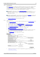
The ps4000SetChannel function allows you to set the voltage range of each input
channel of the scope. Each device in the PicoScope 4000 series has its own set of
voltage ranges described in its data sheet. Each sample is normalized to 16 bits
resulting in values returned to your application as follows:
Constant
Voltage
Value returned
decimal
hex
PS4000_MAX_VALUE
or
PS4262_MAX_VALUE
maximum
32 764
32 767
7FFC
7FFF
N/A
zero
0
0000
PS4000_MIN_VALUE
or
PS4262_MIN_VALUE
minimum
–32 764
–32 767
8004
8001
PS4000_LOST_DATA
Note 1
-32 768
8000
1. In streaming mode, this special value indicates a buffer overrun.
4.4
Channel selection
You can switch each channel on and off, and set its coupling mode to either AC or DC,
using the ps4000SetChannel function.
DC coupling:
The scope accepts all input frequencies from zero (DC) up to its
maximum analogue bandwidth.
AC coupling:
The scope accepts input frequencies from a few hertz up to its
maximum analogue bandwidth. The lower -3 dB cutoff frequency
is about 1 hertz.
4.5
Triggering
PicoScope 4000 Series PC Oscilloscopes can either start collecting data immediately,
or be programmed to wait for a trigger event to occur. In both cases you need to use
the three PicoScope 4000 trigger functions. These can be run collectively by calling
ps4000SetSimpleTrigger, or singularly:
ps4000SetTriggerChannelConditions
ps4000SetTriggerChannelDirections
ps4000SetTriggerChannelProperties
A trigger event can occur when one of the signal or trigger input channels crosses a
threshold voltage on either a rising or a falling edge.
The driver supports these triggering methods:
Simple Edge
Advanced Edge
Windowing
Pulse width
Logic
Delay
Drop-out
Runt