PicoScope 4000 Series PC Oscilloscopes Programmer's Guide ps4000pg.en-6 Copyright © 2008-2011 Pico Technology Ltd. All rights reserved.
PicoScope 4000 Series Programmer's Guide I Contents 1 Welcome .....................................................................................................................................1 2 Introduction .....................................................................................................................................2 ...........................................................................................................................................
II Contents ...........................................................................................................................................41 22 ps4000GetValuesTriggerTimeOffsetBulk64 ...........................................................................................................................................42 23 ps4000HoldOff ...........................................................................................................................................
PicoScope 4000 Series Programmer's Guide 1 1 Welcome The PicoScope 4000 Series of PC Oscilloscopes from Pico Technology is a range of compact, high-resolution scope units designed to replace traditional bench-top oscilloscopes. This manual explains how to use the Application Programming Interface (API) for the PicoScope 4000 Series scopes. For more information on the hardware, see the PicoScope 4000 Series User's Guide available as a separate manual. Copyright © 2008-2011 Pico Technology Ltd.
2 Introduction 2 Introduction 2.1 Software licence conditions The material contained in this release is licensed, not sold. Pico Technology Limited grants a licence to the person who installs this software, subject to the conditions listed below. Access. The licensee agrees to allow access to this software only to persons who have been informed of these conditions and agree to abide by them. Usage.
PicoScope 4000 Series Programmer's Guide 2.3 3 Company details Address: Pico Technology James House Colmworth Business Park St Neots Cambridgeshire PE19 8YP United Kingdom Phone: Fax: +44 (0) 1480 396 395 +44 (0) 1480 396 296 Email: Technical Support: Sales: support@picotech.com sales@picotech.com Web site: www.picotech.com Copyright © 2008-2011 Pico Technology Ltd. All rights reserved. ps4000pg.
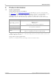
4 Product information 3 Product information 3.1 System requirements Using with PicoScope for Windows To ensure that your PicoScope 4000 Series PC Oscilloscope operates correctly with the PicoScope software, you must have a computer with at least the minimum system requirements to run one of the supported operating systems, as shown in the following table. The performance of the oscilloscope will be better with a more powerful PC. Please note the PicoScope software is not installed as part of the SDK.
PicoScope 4000 Series Programmer's Guide 3.2 5 Installation instructions IMPORTANT Do not connect your PicoScope 4000 Series scope device to the PC before you have installed the Pico Technology software. If you do, Windows might not recognise the scope device correctly. Procedure Follow the instructions in the Installation Guide included with your product package. Connect your PC Oscilloscope to the PC using the USB cable supplied.
6 4 Programming with the PicoScope 4000 Series Programming with the PicoScope 4000 Series The ps4000.dll dynamic link library in your PicoScope installation directory allows you to program a PicoScope 4000 Series oscilloscope using standard C function calls. A typical program for capturing data consists of the following steps: Open the scope unit. Set up the input channels with the required voltage ranges and coupling mode. Set up triggering. Start capturing data.
PicoScope 4000 Series Programmer's Guide 4.3 7 Voltage ranges The ps4000SetChannel function allows you to set the voltage range of each input channel of the scope. Each device in the PicoScope 4000 series has its own set of voltage ranges described in its data sheet.
8 4.6 Programming with the PicoScope 4000 Series Sampling modes PicoScope 4000 Series PC Oscilloscopes can run in various sampling modes. Block mode. In this mode, the scope stores data in internal RAM and then transfers it to the PC. When the data has been collected it is possible to examine the data, with an optional aggregation factor. The data is lost when a new run is started in the same segment, the settings are changed, or the scope is powered down. Rapid block mode.
PicoScope 4000 Series Programmer's Guide 9 Aggregation. When the data has been collected, you can set an optional aggregation factor and examine the data. Aggregation is a process that reduces the amount of data by combining adjacent samples using a maximum/minimum algorithm. It is useful for zooming in and out of the data without having to repeatedly transfer the entire contents of the scope's buffer to the PC. Memory segmentation.
10 4.6.2 Programming with the PicoScope 4000 Series Rapid block mode In normal block mode, the PicoScope 4000 series scopes collect one waveform at a time. You start the the device running, wait until all samples are collected by the device, and then download the data to the PC or start another run. There is a time overhead of tens of milliseconds associated with starting a run, causing a gap between waveforms.
PicoScope 4000 Series Programmer's Guide 4.6.2.2 11 Rapid block mode example 1: no aggregation #define MAX_SAMPLES 1000 Set up the device up as usual.
12 Programming with the PicoScope 4000 Series ps4000GetValuesBulk ( handle, &noOfSamples, // set to MAX_SAMPLES on entering the function 10, // fromSegmentIndex, 19, // toSegmentIndex, overflow // an array of size 10 shorts ) Comments: the number of samples could be up to noOfPreTriggerSamples + noOfPostTriggerSamples, the values set in ps4000RunBlock. The samples are always returned from the first sample taken, unlike the ps4000GetValues function which allows the sample index to be set.
PicoScope 4000 Series Programmer's Guide 4.6.2.3 13 Rapid block mode example 2: using aggregation #define MAX_SAMPLES 1000 Set up the device up as usual.
14 Programming with the PicoScope 4000 Series ); ps4000GetTriggerTimeOffset64 ( handle, &time, &timeUnits, index ) } Comments: each waveform is retrieved one at a time from the driver with an aggregation of 1000. 4.6.3 ETS (Equivalent Time Sampling) Note: ETS mode is not supported by the PicoScope 4262 oscilloscope. ETS is a way of increasing the effective sampling rate of the scope when capturing repetitive signals.
PicoScope 4000 Series Programmer's Guide 4.6.4 15 Streaming mode Streaming mode can capture data without the gaps that occur between blocks when using block mode. It can transfer data to the PC at speeds of up to 6.6 million samples per second (150 nanoseconds per sample), depending on the computer's performance. This makes it suitable for high-speed data acquisition, allowing you to capture long data sets limited only by the computer's memory. Aggregation.
16 4.6.5 Programming with the PicoScope 4000 Series Retrieving stored data You can collect data from the PicoScope 4000 driver with a different aggregation factor when ps4000RunBlock or ps4000RunStreaming has already been called and has successfully captured all the data. Use ps4000GetValuesAsync. 4.7 Oversampling When the oscilloscope is operating at sampling rates less than its maximum, it is possible to oversample.
PicoScope 4000 Series Programmer's Guide 4.8 17 Timebases The API allows you to select one of 230 different timebases related to the maximum sampling rate of the oscilloscope. The timebases allow slow enough sampling in block mode to overlap the streaming sample intervals, so that you can make a smooth transition between block mode and streaming mode.
18 4.9 Programming with the PicoScope 4000 Series Combining several oscilloscopes It is possible to collect data using up to 64 PicoScope 4000 Series PC Oscilloscopes at the same time, depending on the capabilities of the PC. Each oscilloscope must be connected to a separate USB port. The ps4000OpenUnit function returns a handle to an oscilloscope. All the other functions require this handle for oscilloscope identification.
PicoScope 4000 Series Programmer's Guide 4.10 19 API functions The PicoScope 4000 Series API exports the following functions for you to use in your own applications. All functions are C functions using the standard call naming convention (__stdcall). They are all exported with both decorated and undecorated names.
20 Programming with the PicoScope 4000 Series 4.10.1 ps4000BlockReady typedef void (CALLBACK *ps4000BlockReady) ( short handle, PICO_STATUS status, void * pParameter ) This callback function is part of your application. You register it with the PicoScope 4000 series driver using ps4000RunBlock, and the driver calls it back when blockmode data is ready. You can then download the data using the ps4000GetValues function.
PicoScope 4000 Series Programmer's Guide 21 4.10.2 ps4000CloseUnit PICO_STATUS ps4000CloseUnit ( short handle ) This function shuts down a PicoScope 4000 scope device. Applicability All modes Arguments handle, the handle, returned by ps4000OpenUnit, of the scope device to be closed. Returns PICO_OK PICO_HANDLE_INVALID Copyright © 2008-2011 Pico Technology Ltd. All rights reserved. ps4000pg.
22 Programming with the PicoScope 4000 Series 4.10.3 ps4000DataReady typedef void (CALLBACK *ps4000DataReady) ( short handle, long noOfSamples, short overflow, unsigned long triggerAt, short triggered, void * pParameter ) This function handles post-collection data returned by the driver after a call to ps4000GetValuesAsync. It is a callback function that is part of your application.
PicoScope 4000 Series Programmer's Guide 23 4.10.4 ps4000EnumerateUnits PICO_STATUS ( short char short ) ps4000EnumerateUnits * count, * serials, * serialLth This function counts the number of PicoScope 4000 units connected to the computer, and returns a list of serial numbers as a string. Applicability All modes Arguments * count, on exit, the number of scopes found * serials, on exit, a list of serial numbers separated by commas and terminated by a final null.
24 Programming with the PicoScope 4000 Series 4.10.5 ps4000FlashLed PICO_STATUS ps4000FlashLed ( short handle, short start ) This function flashes the LED on the front of the scope without blocking the calling thread. Calls to ps4000RunStreaming and ps4000RunBlock cancel any flashing started by this function. Applicability All modes Arguments handle, the handle of the scope device start, the action required: <0 0 >0 Returns ps4000pg.en : : : flash the LED indefinitely. stop the LED flashing.
PicoScope 4000 Series Programmer's Guide 25 4.10.6 ps4000GetChannelInformation PICO_STATUS ps4000GetChannelInformation ( short handle, PS4000_CHANNEL_INFO info, int probe, int * ranges, int * length, int channel ) This function queries which extra ranges are available on a scope device.
26 Programming with the PicoScope 4000 Series 4.10.7 ps4000GetMaxDownSampleRatio PICO_STATUS ps4000GetMaxDownSampleRatio ( short handle, unsigned long noOfUnaggregatedSamples, unsigned long * maxDownSampleRatio, short downSampleRatioMode, unsigned short segmentIndex ) This function returns the maximum downsampling ratio that can be used for a given number of samples.
PicoScope 4000 Series Programmer's Guide 27 4.10.8 ps4000GetStreamingLatestValues PICO_STATUS ps4000GetStreamingLatestValues ( short handle, ps4000StreamingReady lpPs4000Ready, void * pParameter ) This function is used to collect the next block of values while streaming is running. You must call ps4000RunStreaming beforehand to set up streaming. Applicability Streaming mode only Arguments handle, the handle of the required device.
28 Programming with the PicoScope 4000 Series 4.10.9 ps4000GetTimebase PICO_STATUS ps4000GetTimebase ( short handle, unsigned long timebase, long noSamples, long * timeIntervalNanoseconds, short oversample, long * maxSamples unsigned short segmentIndex ) This function discovers which timebases are available on the oscilloscope. You should set up the channels using ps4000SetChannel first. Applicability All modes Arguments handle, the handle of the required device.
PicoScope 4000 Series Programmer's Guide 29 4.10.10 ps4000GetTimebase2 PICO_STATUS ps4000GetTimebase2 ( short handle, unsigned long timebase, long noSamples, float * timeIntervalNanoseconds, short oversample, long * maxSamples unsigned short segmentIndex ) This function differs from ps4000GetTimebase only in the float * type of the timeIntervalNanoseconds argument. Applicability All modes Arguments timeIntervalNanoseconds, a pointer to the time interval between readings at the selected timebase.
30 Programming with the PicoScope 4000 Series 4.10.11 ps4000GetTriggerChannelTimeOffset PICO_STATUS ps4000GetTriggerChannelTimeOffset ( short handle, unsigned long * timeUpper, unsigned long * timeLower, PS4000_TIME_UNITS * timeUnits, unsigned short segmentIndex, PS4000_CHANNEL channel ) This function gets the time, as two 4-byte values, at which the trigger occurred, adjusted for the time skew of the specified channel relative to the trigger source.
PicoScope 4000 Series Programmer's Guide 31 4.10.12 ps4000GetTriggerChannelTimeOffset64 PICO_STATUS ps4000GetTriggerChannelTimeOffset64 ( short handle, __int64 * time, PS4000_TIME_UNITS * timeUnits, unsigned short segmentIndex, PS4000_CHANNEL channel ) This function gets the time, as a single 8-byte value, at which the trigger occurred, adjusted for the time skew of the specified channel relative to the trigger source.
32 Programming with the PicoScope 4000 Series 4.10.13 ps4000GetTriggerTimeOffset PICO_STATUS ps4000GetTriggerTimeOffset ( short handle unsigned long * timeUpper unsigned long * timeLower PS4000_TIME_UNITS * timeUnits unsigned short segmentIndex ) This function gets the time, as two 4-byte values, at which the trigger occurred. Call it after block-mode data has been captured or when data has been retrieved from a previous block-mode capture.
PicoScope 4000 Series Programmer's Guide 33 4.10.14 ps4000GetTriggerTimeOffset64 PICO_STATUS ps4000GetTriggerTimeOffset64 ( short handle, __int64 * time, PS4000_TIME_UNITS * timeUnits, unsigned short segmentIndex ) This function gets the time, as a single 8-byte value, at which the trigger occurred. Call it after block-mode data has been captured or when data has been retrieved from a previous block-mode capture.
34 Programming with the PicoScope 4000 Series 4.10.15 ps4000GetUnitInfo PICO_STATUS ps4000GetUnitInfo ( short handle, char * string, short stringLength, short * requiredSize PICO_INFO info ) This function writes information about the specified scope device to a character string. If the device fails to open, only the driver version and error code are available to explain why the last open unit call failed.
PicoScope 4000 Series Programmer's Guide 35 4.10.16 ps4000GetValues PICO_STATUS ps4000GetValues ( short handle, unsigned long startIndex, unsigned long * noOfSamples, unsigned long downSampleRatio, short downSampleRatioMode, unsigned short segmentIndex, short * overflow ) This function returns block-mode data, either with or without aggregation, starting at the specified sample number. It is used to get the stored data from the scope after data collection has stopped.
36 Programming with the PicoScope 4000 Series 4.10.17 ps4000GetValuesAsync PICO_STATUS ps4000GetValuesAsync ( short handle, unsigned long startIndex, unsigned long noOfSamples, unsigned long downSampleRatio, short downSampleRatioMode, unsigned short segmentIndex, void * lpDataReady, void * pParameter ) This function returns streaming data, either with or without aggregation, starting at the specified sample number. It is used to get the stored data from the scope after data collection has stopped.
PicoScope 4000 Series Programmer's Guide 37 4.10.18 ps4000GetValuesBulk PICO_STATUS ps4000GetValuesBulk ( short handle, unsigned long * noOfSamples, unsigned short fromSegmentIndex, unsigned short toSegmentIndex, short * overflow ) This function allows more than one waveform to be retrieved at a time in rapid block mode. The waveforms must have been collected sequentially and in the same run. This method of collection does not support aggregation.
38 Programming with the PicoScope 4000 Series 4.10.
PicoScope 4000 Series Programmer's Guide 39 4.10.20 ps4000GetValuesTriggerChannelTimeOffsetBulk64 PICO_STATUS ps4000GetValuesTriggerChannelTimeOffsetBulk64 ( short handle, __int64 * times, PS4000_TIME_UNITS * timeUnits, unsigned short fromSegmentIndex, unsigned short toSegmentIndex, PS4000_CHANNEL channel ) This function retrieves the time offset, as a 64-bit integer, for a group of waveforms captured in rapid block mode, adjusted for the time skew relative to the trigger source.
40 Programming with the PicoScope 4000 Series 4.10.21 ps4000GetValuesTriggerTimeOffsetBulk PICO_STATUS ps4000GetValuesTriggerTimeOffsetBulk ( short handle, unsigned long * timesUpper, unsigned long * timesLower, PS4000_TIME_UNITS * timeUnits, unsigned short fromSegmentIndex, unsigned short toSegmentIndex ) This function retrieves the time offset, as lower and upper 32-bit values, for a group of waveforms obtained in rapid block mode.
PicoScope 4000 Series Programmer's Guide 41 4.10.22 ps4000GetValuesTriggerTimeOffsetBulk64 PICO_STATUS ps4000GetValuesTriggerTimeOffsetBulk64 ( short handle, __int64 * times, PS4000_TIME_UNITS * timeUnits, unsigned short fromSegmentIndex, unsigned short toSegmentIndex ) This function retrieves the time offset, as a 64-bit integer, for a group of waveforms captured in rapid block mode. The array size of times must be greater than or equal to the number of waveform time offsets requested.
42 Programming with the PicoScope 4000 Series 4.10.23 ps4000HoldOff PICO_STATUS ps4000HoldOff ( short handle, u_int64_t holdoff, PS4000_HOLDOFF_TYPE type ) This function sets the holdoff time - the time that the scope waits after each trigger event before allowing the next trigger event. Applicability All trigger modes Arguments holdoff, the number of samples between trigger events. The time is calculated by multiplying the sample interval by the holdoff. type, the type of hold-off.
PicoScope 4000 Series Programmer's Guide 43 4.10.24 ps4000IsLedFlashing PICO_STATUS ps4000IsLedFlashing ( short handle, short * status ) This function reports whether or not the LED is flashing. Applicability All modes Arguments handle, the handle of the scope device status, returns a flag indicating the status of the LED: <> 0 : flashing 0 : not flashing Returns PICO_OK PICO_HANDLE_INVALID PICO_NULL_PARAMETER Copyright © 2008-2011 Pico Technology Ltd. All rights reserved. ps4000pg.
44 Programming with the PicoScope 4000 Series 4.10.25 ps4000IsReady PICO_STATUS ps4000IsReady ( short handle, short * ready ) This function may be used instead of a callback function to receive data from ps4000RunBlock. To use this method, pass a NULL pointer as the lpReady argument to ps4000RunBlock. You must then poll the driver to see if it has finished collecting the requested samples.
PicoScope 4000 Series Programmer's Guide 45 4.10.26 ps4000IsTriggerOrPulseWidthQualifierEnabled PICO_STATUS ps4000IsTriggerOrPulseWidthQualifierEnabled ( short handle, short * triggerEnabled, short * pulseWidthQualifierEnabled ) This function discovers whether a trigger, or pulse width triggering, is enabled. Applicability Call after setting up the trigger, and just before calling either ps4000RunBlock or ps4000RunStreaming.
46 Programming with the PicoScope 4000 Series 4.10.27 ps4000MemorySegments PICO_STATUS ps4000MemorySegments ( short handle unsigned short nSegments, long * nMaxSamples ) This function sets the number of memory segments that the scope device will use. By default, each capture fills the scope device's available memory. This function allows you to divide the memory into a number of segments so that the scope can store several captures sequentially.
PicoScope 4000 Series Programmer's Guide 47 4.10.28 ps4000NoOfStreamingValues PICO_STATUS ps4000NoOfStreamingValues ( short handle, unsigned long * noOfValues ) This function returns the available number of samples from a streaming run. Applicability Streaming mode. Call after ps4000Stop.
48 Programming with the PicoScope 4000 Series 4.10.29 ps4000OpenUnit PICO_STATUS ps4000OpenUnit ( short * handle ) This function opens a scope device. The maximum number of units that can be opened is determined by the operating system, the kernel driver and the PC's hardware.
PicoScope 4000 Series Programmer's Guide 49 4.10.30 ps4000OpenUnitAsync PICO_STATUS ps4000OpenUnitAsync ( short * status ) This function opens a scope device without blocking the calling thread. You can find out when it has finished by periodically calling ps4000OpenUnitProgress until that function returns a non-zero value.
50 Programming with the PicoScope 4000 Series 4.10.31 ps4000OpenUnitAsyncEx PICO_STATUS ps4000OpenUnitAsyncEx ( short * status, char * serial ) This function opens a scope device selected by serial number without blocking the calling thread. You can find out when it has finished by periodically calling ps4000OpenUnitProgress until that function returns a non-zero value.
PicoScope 4000 Series Programmer's Guide 51 4.10.32 ps4000OpenUnitEx PICO_STATUS ps4000OpenUnitEx ( short * handle, char * serial ) This function opens a scope device. The maximum number of units that can be opened is determined by the operating system, the kernel driver and the PC's hardware.
52 Programming with the PicoScope 4000 Series 4.10.33 ps4000OpenUnitProgress PICO_STATUS ps4000OpenUnitProgress ( short * handle, short * progressPercent, short * complete ) This function checks on the progress of ps4000OpenUnitAsync. Applicability Use after ps4000OpenUnitAsync Arguments handle, pointer to a short where the unit handle is to be written. 1 if the unit fails to open, 0 if no unit is found or a non-zero handle to the device.
PicoScope 4000 Series Programmer's Guide 53 4.10.34 ps4000RunBlock PICO_STATUS ps4000RunBlock ( short handle, long noOfPreTriggerSamples, long noOfPostTriggerSamples, unsigned long timebase, short oversample, long * timeIndisposedMs, unsigned short segmentIndex, ps4000BlockReady lpReady, void * pParameter ) This function starts a collection of data points (samples) in block mode. The number of samples is determined by noOfPreTriggerSamples and noOfPostTriggerSamples (see below for details).
54 Programming with the PicoScope 4000 Series Applicability Block mode, rapid block mode Arguments handle, the handle of the required device. noOfPreTriggerSamples, the number of samples to return before the trigger event. If no trigger has been set then this argument is ignored and noOfPostTriggerSamples specifies the maximum number of data points (samples) to collect. noOfPostTriggerSamples, the number of samples to be taken after a trigger event.
PicoScope 4000 Series Programmer's Guide 55 4.10.35 ps4000RunStreaming PICO_STATUS ps4000RunStreaming ( short handle, unsigned long * sampleInterval, PS4000_TIME_UNITS sampleIntervalTimeUnits unsigned long maxPreTriggerSamples, unsigned long maxPostTriggerSamples, short autoStop unsigned long downSampleRatio, unsigned long overviewBufferSize ) This function tells the oscilloscope to start collecting data in streaming mode.
56 Programming with the PicoScope 4000 Series Applicability Streaming mode only Arguments handle, the handle of the required device. sampleInterval, a pointer to the requested time interval between data points on entry and the actual time interval assigned on exit. sampleIntervalTimeUnits, the unit of time that the sampleInterval is set to.
PicoScope 4000 Series Programmer's Guide 57 4.10.36 ps4000RunStreamingEx PICO_STATUS ps4000RunStreamingEx ( short handle, unsigned long * sampleInterval, PS4000_TIME_UNITS sampleIntervalTimeUnits unsigned long maxPreTriggerSamples, unsigned long maxPostTriggerSamples, short autoStop unsigned long downSampleRatio, short downSampleRatioMode, unsigned long overviewBufferSize ) This function tells the oscilloscope to start collecting data in streaming mode and with a specified data reduction mode.
58 Programming with the PicoScope 4000 Series Applicability Streaming mode only Arguments handle, the handle of the required device. sampleInterval, a pointer to the requested time interval between data points on entry and the actual time interval assigned on exit. sampleIntervalTimeUnits, the unit of time that the sampleInterval is set to.
PicoScope 4000 Series Programmer's Guide 59 4.10.37 ps4000SetBwFilter PICO_STATUS ps4000SetBwFilter ( short handle, PS4000_CHANNEL channel, short enable ) This function enables or disables the bandwidth-limiting filter on the specified channel. Applicability PicoScope 4262 only Arguments handle, the handle of the required device channel, an enumerated type.
60 Programming with the PicoScope 4000 Series 4.10.38 ps4000SetChannel PICO_STATUS ps4000SetChannel ( short handle, PS4000_CHANNEL channel, short enabled, short dc, PS4000_RANGE range ) This function specifies whether an input channel is to be enabled, the AC/DC coupling mode and the voltage range. Applicability All modes Arguments handle, the handle of the required device channel, an enumerated type.
PicoScope 4000 Series Programmer's Guide 61 4.10.39 ps4000SetDataBuffer PICO_STATUS ps4000SetDataBuffer ( short handle, PS4000_CHANNEL channel, short * buffer, long bufferLth ) This function registers your data buffer, for non-aggregated data, with the PicoScope 4000 driver. You need to allocate the buffer before calling this function. Applicability All modes. For aggregated data, use ps4000SetDataBuffers instead.
62 Programming with the PicoScope 4000 Series 4.10.40 ps4000SetDataBufferBulk PICO_STATUS ps4000SetDataBufferBulk ( short handle, PS4000_CHANNEL channel, short * buffer, long bufferLth, unsigned short waveform ) This function allows the buffers to be set for each waveform in rapid block mode. The number of waveforms captured is determined by the nCaptures argument sent to ps4000SetNoOfCaptures. There is only one buffer for each waveform, because bulk collection does not support aggregation.
PicoScope 4000 Series Programmer's Guide 63 4.10.41 ps4000SetDataBuffers PICO_STATUS ps4000SetDataBuffers ( short handle, PS4000_CHANNEL channel, short * bufferMax, short * bufferMin, long bufferLth ) This function registers your data buffers, for receiving aggregated data, with the PicoScope 4000 driver. You need to allocate memory for the buffers before calling this function. Applicability All sampling modes. For non-aggregated data, use ps4000SetDataBuffer instead.
64 Programming with the PicoScope 4000 Series 4.10.42 ps4000SetDataBuffersWithMode PICO_STATUS ps4000SetDataBuffersWithMode ( short handle, PS4000_CHANNEL channel, short * bufferMax, short * bufferMin, long bufferLth, RATIO_MODE mode ) This function registers your data buffers, for receiving aggregated data, with the PicoScope 4000 driver. You need to allocate memory for the buffers before calling this function. Applicability All sampling modes. For non-aggregated data, use ps4000SetDataBuffer instead.
PicoScope 4000 Series Programmer's Guide 65 4.10.43 ps4000SetDataBufferWithMode PICO_STATUS ps4000SetDataBufferWithMode ( short handle, PS4000_CHANNEL channel, short * buffer, long bufferLth, RATIO_MODE mode ) This function registers your data buffer, for non-aggregated data, with the PicoScope 4000 driver. You need to allocate the buffer before calling this function. Applicability All modes. For aggregated data, use ps4000SetDataBuffers instead.
66 Programming with the PicoScope 4000 Series 4.10.44 ps4000SetEts PICO_STATUS ps4000SetEts ( short handle, PS4000_ETS_MODE mode, short etsCycles, short etsInterleave, long * sampleTimePicoseconds ) This function is used to enable or disable ETS (equivalent time sampling) and to set the ETS parameters. Applicability Block mode only. ETS is not supported by PicoScope 4262. Arguments handle, the handle of the required device mode, the ETS mode.
PicoScope 4000 Series Programmer's Guide 67 4.10.45 ps4000SetEtsTimeBuffer PICO_STATUS ( short __int64 * long ) ps4000SetEtsTimeBuffer handle, buffer, bufferLth This function tells the PicoScope 4000 driver where to find your application's ETS time buffers. These buffers contain the 64-bit timing information for each ETS sample after you run a block-mode ETS capture. Applicability ETS mode only. ETS mode is not supported by the PicoScope 4262 oscilloscope.
68 Programming with the PicoScope 4000 Series 4.10.46 ps4000SetEtsTimeBuffers PICO_STATUS ps4000SetEtsTimeBuffers ( short handle, unsigned long * timeUpper, unsigned long * timeLower, long bufferLth ) This function tells the PicoScope 4000 driver where to find your application's ETS time buffers. These buffers contain the timing information for each ETS sample after you run a block-mode ETS capture.
PicoScope 4000 Series Programmer's Guide 69 4.10.47 ps4000SetExtTriggerRange PICO_STATUS ps4000SetExtTriggerRange ( short handle, PS4000_RANGE extRange ) This function sets the range of the external trigger. Applicability PicoScope 4262 only Arguments handle, the handle of the required oscilloscope extRange, specifies the range for the external trigger (±500 mV or ±5 V) Returns 5 8 PICO_OK PICO_INVALID_PARAMETER extRange PS4000_500MV PS4000_5V Copyright © 2008-2011 Pico Technology Ltd.
70 Programming with the PicoScope 4000 Series 4.10.48 ps4000SetNoOfCaptures PICO_STATUS ps4000SetNoOfCaptures ( short handle, unsigned short nCaptures ) This function sets the number of captures to be collected in one run of rapid block mode. If you do not call this function before a run, the driver will capture one waveform. ps4000pg.
PicoScope 4000 Series Programmer's Guide 71 4.10.49 ps4000SetPulseWidthQualifier PICO_STATUS ps4000SetPulseWidthQualifier ( short handle, PWQ_CONDITIONS * conditions, short nConditions, THRESHOLD_DIRECTION direction, unsigned long lower, unsigned long upper, PULSE_WIDTH_TYPE type ) This function sets up pulse width qualification, which can be used on its own for pulse width triggering or combined with window triggering to produce more complex triggers.
72 Programming with the PicoScope 4000 Series 4.10.49.1 PWQ_CONDITIONS structure A structure of this type is passed to ps4000SetPulseWidthQualifier in the conditions argument to specify the trigger conditions, and is defined as follows: - typedef struct tPwqConditions { TRIGGER_STATE channelA; TRIGGER_STATE channelB; TRIGGER_STATE channelC; TRIGGER_STATE channelD; TRIGGER_STATE external; TRIGGER_STATE aux; } PWQ_CONDITIONS Each structure is the logical AND of the states of the scope's inputs.
PicoScope 4000 Series Programmer's Guide 73 4.10.
74 Programming with the PicoScope 4000 Series dwellCount, the time, in 50 ns steps, between successive additions of deltaPhaseIncrement to the delta phase counter. This determines the rate at which the generator sweeps the output frequency. arbitraryWaveform, a pointer to a buffer that holds the waveform pattern as a set of samples equally spaced in time.
PicoScope 4000 Series Programmer's Guide 75 4.10.50.1 AWG index modes The arbitrary waveform generator supports single, dual and quad index modes to make the best use of the waveform buffer. Single mode. The generator outputs the raw contents of the buffer repeatedly. This mode is the only one that can generate asymmetrical waveforms. You can also use this mode for symmetrical waveforms, but the dual and quad modes make more efficient use of the buffer memory. Dual mode.
76 Programming with the PicoScope 4000 Series 4.10.
PicoScope 4000 Series Programmer's Guide 77 sweepType, specifies whether the frequency should sweep from startFrequency to stopFrequency, or in the opposite direction, or repeatedly reverse direction. Use one of these values of the enumerated type enPS4000SweepType: PS4000_UP PS4000_DOWN PS4000_UPDOWN PS4000_DOWNUP operationType, configures the white noise/PRBS generator: PS4000_OP_NONE: white noise/PRBS output disabled. The waveform is defined by the waveType argument.
78 Programming with the PicoScope 4000 Series 4.10.52 ps4000SetSimpleTrigger PICO_STATUS ps4000SetSimpleTrigger ( short handle, short enable, PS4000_CHANNEL source, short threshold, THRESHOLD_DIRECTION direction, unsigned long delay, short autoTrigger_ms ) This function simplifies arming the trigger. It supports only the LEVEL trigger types and does not allow more than one channel to have a trigger applied to it. Any previous pulse width qualifier is cancelled.
PicoScope 4000 Series Programmer's Guide 79 4.10.53 ps4000SetTriggerChannelConditions PICO_STATUS ps4000SetTriggerChannelConditions ( short handle, TRIGGER_CONDITIONS * conditions, short nConditions ) This function sets up trigger conditions on the scope's inputs. The trigger is set up by defining one or more TRIGGER_CONDITIONS structures that are then ORed together. Each structure is itself the AND of the states of one or more of the inputs.
80 Programming with the PicoScope 4000 Series 4.10.53.
PicoScope 4000 Series Programmer's Guide 81 4.10.54 ps4000SetTriggerChannelDirections PICO_STATUS ps4000SetTriggerChannelDirections ( short handle, THRESHOLD_DIRECTION channelA, THRESHOLD_DIRECTION channelB, THRESHOLD_DIRECTION channelC, THRESHOLD_DIRECTION channelD, THRESHOLD_DIRECTION ext, THRESHOLD_DIRECTION aux ) This function sets the direction of the trigger for each channel. Applicability All modes.
82 Programming with the PicoScope 4000 Series 4.10.55 ps4000SetTriggerChannelProperties PICO_STATUS ps4000SetTriggerChannelProperties ( short handle, TRIGGER_CHANNEL_PROPERTIES * channelProperties short nChannelProperties short auxOutputEnable, long autoTriggerMilliseconds ) This function is used to enable or disable triggering and set its parameters. Applicability All modes Arguments handle, the handle of the required device.
PicoScope 4000 Series Programmer's Guide 83 4.10.55.
84 Programming with the PicoScope 4000 Series 4.10.56 ps4000SetTriggerDelay PICO_STATUS ps4000SetTriggerDelay ( short handle, unsigned long delay ) This function sets the post-trigger delay, which causes capture to start a defined time after the trigger event. Applicability All modes Arguments handle, the handle of the required device delay, the time between the trigger occurring and the first sample, in sample periods.
PicoScope 4000 Series Programmer's Guide 85 4.10.57 ps4000SigGenSoftwareControl PICO_STATUS ps4000SigGenSoftwareControl ( short handle, short state ) This function causes a trigger event, or starts and stops gating. It is used when the signal generator is set to SIGGEN_SOFT_TRIG . Applicability Use with ps4000SetSigGenBuiltIn or ps4000SetSigGenArbitrary.
86 Programming with the PicoScope 4000 Series 4.10.58 ps4000Stop PICO_STATUS ps4000Stop ( short handle ) This function stops the scope device from sampling data. If this function is called before a trigger event occurs, the oscilloscope may not contain valid data. Always call this function after the end of a capture to ensure that the scope is ready for the next capture. Applicability All modes Arguments handle, the handle of the required device.
PicoScope 4000 Series Programmer's Guide 87 4.10.59 ps4000StreamingReady typedef void (CALLBACK *ps4000StreamingReady) ( short handle, long noOfSamples, unsigned long startIndex, short overflow, unsigned long triggerAt, short triggered, short autoStop, void * pParameter ) This callback function is part of your application. You register it with the PicoScope 4000 series driver using ps4000GetStreamingLatestValues, and the driver calls it back when streaming-mode data is ready.
88 4.11 Programming with the PicoScope 4000 Series Enumerated types and constants The following types and constants are defined in the file ps4000Api.h, which is included in the SDK.
PicoScope 4000 Series Programmer's Guide 89 typedef enum enPS4000Range { PS4000_10MV, PS4000_20MV, PS4000_50MV, PS4000_100MV, PS4000_200MV, PS4000_500MV, PS4000_1V, PS4000_2V, PS4000_5V, PS4000_10V, PS4000_20V, PS4000_50V, PS4000_100V, PS4000_MAX_RANGES, PS4000_RESISTANCE_100R = PS4000_MAX_RANGES, PS4000_RESISTANCE_1K, PS4000_RESISTANCE_10K, PS4000_RESISTANCE_100K, PS4000_RESISTANCE_1M, PS4000_MAX_RESISTANCES, PS4000_ACCELEROMETER_10MV = PS4000_MAX_RESISTANCES, PS4000_ACCELEROMETER_20MV, PS4000_ACCELEROME
90 Programming with the PicoScope 4000 Series P_PRESSURE_SENSOR_5BAR, P_OPTICAL_SWITCH, P_UNKNOWN, P_MAX_PROBES = P_UNKNOWN } PS4000_PROBE; typedef enum enPS4000ChannelInfo { CI_RANGES, CI_RESISTANCES, CI_ACCELEROMETER, CI_PROBES, CI_TEMPERATURES } PS4000_CHANNEL_INFO; typedef enum enPS4000EtsMode { PS4000_ETS_OFF, PS4000_ETS_FAST, PS4000_ETS_SLOW, PS4000_ETS_MODES_MAX } PS4000_ETS_MODE; // ETS disabled typedef enum enPS4000TimeUnits { PS4000_FS, PS4000_PS, PS4000_NS, PS4000_US, PS4000_MS, PS4000_S, PS4
PicoScope 4000 Series Programmer's Guide 91 PS4000_HALF_SINE, PS4000_DC_VOLTAGE, PS4000_WHITE_NOISE, MAX_WAVE_TYPES } WAVE_TYPE; typedef enum enSigGenTrigType { SIGGEN_RISING, SIGGEN_FALLING, SIGGEN_GATE_HIGH, SIGGEN_GATE_LOW } SIGGEN_TRIG_TYPE; typedef enum enSigGenTrigSource { SIGGEN_NONE, SIGGEN_SCOPE_TRIG, SIGGEN_AUX_IN, SIGGEN_EXT_IN, SIGGEN_SOFT_TRIG } SIGGEN_TRIG_SOURCE; typedef enum enIndexMode { SINGLE, DUAL, QUAD, MAX_INDEX_MODES } INDEX_MODE; typedef enum enThresholdMode { LEVEL, WINDOW } THRES
92 Programming with the PicoScope 4000 Series NONE = RISING } THRESHOLD_DIRECTION; typedef enum enTriggerState { CONDITION_DONT_CARE, CONDITION_TRUE, CONDITION_FALSE, CONDITION_MAX } TRIGGER_STATE; #pragma pack(1) typedef struct tTriggerConditions { TRIGGER_STATE channelA; TRIGGER_STATE channelB; TRIGGER_STATE channelC; TRIGGER_STATE channelD; TRIGGER_STATE external; TRIGGER_STATE aux; TRIGGER_STATE pulseWidthQualifier; } TRIGGER_CONDITIONS; #pragma pack() #pragma pack(1) typedef struct tPwqConditions { T
PicoScope 4000 Series Programmer's Guide 93 PW_TYPE_GREATER_THAN, PW_TYPE_IN_RANGE, PW_TYPE_OUT_OF_RANGE } PULSE_WIDTH_TYPE; typedef enum enPs4000HoldOffType { PS4000_TIME, PS4000_MAX_HOLDOFF_TYPE } PS4000_HOLDOFF_TYPE; typedef enum enPS4000FrequencyCounterRange { FC_2K, FC_20K, FC_20, FC_200, FC_MAX } PS4000_FREQUENCY_COUNTER_RANGE; ps4 0 0 0 A pi.h issue: 1 .3 6 8 /9 /2 0 1 1 Copyright © 2008-2011 Pico Technology Ltd. All rights reserved. ps4000pg.
94 4.12 Programming with the PicoScope 4000 Series Driver error codes This description of the driver error codes is aimed at those people who intend to write their own programs for use with the driver. Every function in the ps4000.dll driver returns an error code from the following list of PICO_STATUS values. They are declared in the picoStatus.h header file supplied with the SDK. Code Enum (hex) 00 PICO_OK. The PicoScope 4000 is functioning correctly. 01 PICO_MAX_UNITS_OPENED.
PicoScope 4000 Series Programmer's Guide 1D 95 PICO_TOO_MANY_SAMPLES. Number of samples requested is more than available in the current memory segment. 1E 1F 20 21 22 23 24 25 26 27 28 29 2A 2B PICO_TOO_MANY_SEGMENTS. Not possible to create number of segments requested. PICO_PULSE_WIDTH_QUALIFIER. A null pointer has been passed in the trigger function or one of the parameters is out of range. PICO_DELAY. One or more of the hold-off parameters are out of range. PICO_SOURCE_DETAILS.
96 Programming with the PicoScope 4000 Series 3D 3F PICO_GET_VALUES_INTERRUPTED 40 PICO_NOT_USED. The function is not available. PICO_INVALID_SAMPLERATIO. The aggregation ratio requested is out of range. 41 42 PICO_INVALID_STATE. Device is in an invalid state. PICO_NOT_ENOUGH_SEGMENTS. The number of segments allocated is fewer than 43 the number of captures requested. PICO_DRIVER_FUNCTION. You called a driver function while another driver function was still being processed.
PicoScope 4000 Series Programmer's Guide 4.13 97 Programming examples Your PicoScope installation includes programming examples in the following languages and development environments: C Excel LabView 4.13.1 C The SDK includes a console-mode program (ps4000con.c) that demonstrates how to use the PicoScope 4000 driver in Windows.
98 Programming with the PicoScope 4000 Series 4.13.3 LabView The SDK contains a library of VIs that can be used to control the PicoScope 4000 and some simple examples of using these VIs in streaming mode, block mode and rapid block mode. The LabVIEW library (PicoScope4000.llb) can be placed in the user.lib subdirectory to make the VIs available on the ‘User Libraries’ palette. You must also copy ps4000.dll and ps4000wrap.dll to the folder containing your LabView project.
PicoScope 4000 Series Programmer's Guide 99 PicoScope4000GetRapidBlock.vi - collects a set of data blocks or captures from the oscilloscope in rapid block mode This VI is similar to PicoScope4000GetBlock.vi. It outputs two-dimensional arrays for each channel that contain data from all the requested number of captures. PicoScope4000GetStreamingValues.
100 5 Glossary Glossary AC/DC switch. To switch from AC coupling to DC coupling, or vice versa, select AC or DC from the control on the PicoScope toolbar. The AC setting filters out very lowfrequency components of the input signal, including DC, and is suitable for viewing small AC signals superimposed on a DC or slowly changing offset. In this mode you can measure the peak-to-peak amplitude of an AC signal but not its absolute value. Use the DC setting for measuring the absolute value of a signal. ADC.
PicoScope 4000 Series Programmer's Guide 101 Maximum sampling rate. A figure indicating the maximum number of samples the oscilloscope can acquire per second. The higher the sampling rate of the oscilloscope, the more accurate the representation of the high-frequency details in a fast signal. MS/s. Megasample (million samples) per second. Oversampling. Oversampling is taking measurements more frequently than the requested sample rate, and then combining them to produce the required number of samples.
PicoScope 4000 Series Programmer's Guide 103 Index setting time buffers setting up 66 using (API) Excel A AC/DC coupling setting 60 Filter, bandwidth-limiting Function calls 19 API function calls 19 Arbitrary waveform generator index modes 75 73 73 Bandwidth-limiting filter Block mode 7, 8, 9, 20 polling status 44 starting 59 Functions ps4000BlockReady 20 ps4000CloseUnit 21 ps4000DataReady 22 ps4000EnumerateUnits 59 ps4000GetStreamingLatestValues ps4000GetTriggerChannelTimeOffset64 7 ps4000G
104 Index Functions ps4000SetDataBuffersWithMode ps4000SetDataBufferWithMode picopp.
PicoScope 4000 Series Programmer's Guide Time buffers setting for ETS 105 67, 68 Timebase 17 setting 28, 29 Trademarks 2 Trigger 7 conditions 79, 80 delay 84 directions 81 pulse width qualifier 45, 71 pulse width qualifier conditions setting up time offset 72 78 30, 31, 32, 33 TRIGGER_CHANNEL_PROPERTIES structure TRIGGER_CONDITIONS structure 83 80 U USB 4, 6 changing ports hub 18 5 V Vertical resolution Voltage ranges 16 7 W WINDOW constant Windows, Microsoft 83 4 Copyright © 2008-2011 Pic
PicoScope 4000 Series Programmer's Guide Copyright © 2008-2011 Pico Technology Ltd. All rights reserved. 107 ps4000pg.
Pico Technology James House Colmworth Business Park ST. NEOTS Cambridgeshire PE19 8YP United Kingdom Tel: +44 (0) 1480 396 395 Fax: +44 (0) 1480 396 296 www.picotech.com ps4000pg.en-6 12.9.11 Copyright © 2008-2011 Pico Technology Ltd. All rights reserved.