
User Manual

ADC-20/ADC-24 User's Guide 12
Copyright © 2005-2010 Pico Technology Ltd. All rights reserved. adc20.en
4.3
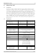
Analog connector
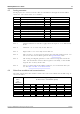
Analog inputs are connected to the ADC-20 and ADC-24 through the female DB25
connector. The connections are as follows:
Pin
Function
Pin
Function
1
Channel 2 (Channel 1-)
14
Channel 1
2
Channel 4 (Channel 3-)
15
Channel 3
3
Channel 6 (Channel 5-)
16
Channel 5
4
Channel 8 (Channel 7-)
17
Channel 7
5
Channel 10 (Channel 9-)
18
Channel 9
6
Channel 12 (Channel 11-)
19
Channel 11
7
Channel 14 (Channel 13-)
20
Channel 13
8
Channel 16 (Channel 15-)
21
Channel 15
9
Analog Ground
22
Digital Ground
10
+5 volts
23
Digital I/O 1
11
-5 volts
24
Digital I/O 2
12
+2.5 volts
25
Digital I/O 3
13
Digital I/O 4
Note 1: Channel numbers in brackets apply when the input is set to differential
mode.
Note 2: Channels 9 to 16 exist only on the ADC-24.
Note 3: Digital I/Os 1 to 4 exist only on the ADC-24.
Note 4: Pins 10 and 11 are low-current outputs for powering small sensors. Do
not exceed the current limits given in the Specifications table.
Note 5: The analog and digital grounds are not connected together inside the
unit. You should not connect them together externally, as this would
degrade the accuracy of the unit.
Note 6: For easy connection to the DB25 connector, we recommend that you
use the ADC-20/ADC-24 terminal board.
4.4
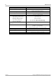
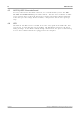
Noise-free resolution and conversion time
The table below shows the number of noise-free bits of resolution for the full range of
conversion times.
Conversion
time
per
channel
Voltage range
& Noise-free resolution (bits)
39 mV
78 mV
156 mV
313 mV
625 mV
±1250 mV
2500 mV
ADC-24 only
ADC-20 and ADC-24
660 ms
17
18
19
20
20
20
20
340 ms
17
18
19
19
19
20
20
180 ms
16
17
18
19
19
19
19
100 ms
16
17
18
18
18
19
19
60 ms
15
16
17
18
18
18
18