ADC-20/ADC-24 High-Resolution Data Loggers User's Guide adc20.en-3 Copyright © 2005-2010 Pico Technology Ltd. All rights reserved.
I Contents Contents 1 Introduction .....................................................................................................................................1 1 Overview 2 Notices ...........................................................................................................................................1 .....................................................................................................................................2 1 Safety warning .....................
ADC-20/ADC-24 User's Guide II 16 HRDLSetDigitalIOChannel...........................................................................................................................................33 (ADC-24 only) ...........................................................................................................................................35 17 HRDLSetInterval .........................................................................................................................................
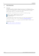
1 Introduction 1 Introduction 1.1 Overview The ADC-20 and ADC-24 High-Resolution Data Loggers are multichannel, highaccuracy USB data loggers for use with PCs. They require no external power supply and take up no expansion slots. They come complete with PicoLog, a program offering all the features of a stand-alone data logger.
ADC-20/ADC-24 User's Guide 2 Notices 2.1 Safety warning 2 We strongly recommend that you read the general safety information below before using your product for the first time. If the equipment is not used in the manner specified, then the protection provided may be impaired. This could result in damage to your computer and/or injury to yourself or others. Maximum input range. The ADC-20 and ADC-24 are designed to measure voltages in the range +/-2.
3 2.2 Notices Legal information The material contained in this release is licensed, not sold. Pico Technology Limited grants a licence to the person who installs this software, subject to the conditions listed below. Access. The licensee agrees to allow access to this software only to persons who have been informed of these conditions and agree to abide by them. Usage. The software in this release is for use only with Pico products or with data collected using Pico products. Copyright.
ADC-20/ADC-24 User's Guide 2.5 4 Trademarks Pico Technology Limited and PicoLog are trademarks of Pico Technology Limited, registered in the United Kingdom and other countries. Pico Technology acknowledges the following product names as trademarks of their respective owners: Windows, Excel, Visual Basic, LabVIEW, Agilent VEE, Delphi. 2.6 Updates We provide upgrades, free of charge, from our web site. We reserve the right to charge for updates or replacements sent out on physical media. 2.
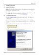
5 Getting started 3 Getting started 3.1 Installing the software Before you connect the ADC-20 or ADC-24 to your computer for the first time, you must install the software supplied on the CD. Insert the Software and Reference CD, then follow the "Install Software" link. You may choose to install the driver when you install the PicoLog software, by ticking the box labelled "32 Bit Drivers" during the installation procedure. Alternatively, you can download the driver from our website at www.picotech.com.
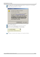
ADC-20/ADC-24 User's Guide 6 In the "Welcome to the New Hardware Found Wizard" dialog (above), click Next>. Wait while the wizard installs the software. A dialog will appear like the one below: Click Continue Anyway. Continue to wait while the wizard installs the software. When instructed, click Finish to close the wizard. After a few seconds you should see this message: Your ADC-20 or ADC-24 Data Logger is now properly installed. Copyright © 2005-2010 Pico Technology Ltd. All rights reserved. adc20.
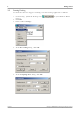
7 3.3 Getting started Starting PicoLog To check that the data logger is working, start the PicoLog application as follows: 1. Start PicoLog. (Click the PicoLog icon: menu.) 2. Click File 3. Point to New settings: in your Windows Start 4. At the Recording dialog, click OK: 5. At the Sampling Rate dialog, click OK: adc20.en Copyright © 2005-2010 Pico Technology Ltd. All rights reserved.
ADC-20/ADC-24 User's Guide 8 6. In the Converter details dialog, set the Converter type to High Resolution Data Logger. The device type and serial number should appear in the USB Devices list, and the USB enumeration progress indicator should gradually move towards 100%. If the progress indicator does not start moving, disconnect and reconnect the unit and then press Refresh. 7. Click OK 8. At the ADC-20 (or ADC-24) channels dialog, double-click on "Channel 1": 9.
9 Getting started 10. Back at the ADC-20 (or ADC-24) Channels dialog, click OK 11. The PLW Recorder view should now display the voltage on channel 1 (near 0 mV if nothing connected): 12. Connect a suitable voltage (for example, from a 1.5 V battery) to the channel. Pin connections are marked on the logger and also listed in the Analog connector topic. adc20.en Copyright © 2005-2010 Pico Technology Ltd. All rights reserved.
ADC-20/ADC-24 User's Guide 4 About the unit 4.1 Introduction 10 The ADC-20 and ADC-24 High-Resolution Data Loggers offer the ultimate in precise and accurate readings. Features such as true differential inputs, galvanic isolation and software-selectable sample rates all contribute to a superior noise-free resolution. The ADC-20 is equipped with a 20-bit A/D converter, and can maintain a gain error of 0.2%.
11 About the unit ADC-20 Isolation (input to input) Isolation (input to ground) Reference output Power outputs ADC-24 None Galvanic, up to +/- 30 V AGND and DGND isolated +2.5 V ±2.5 mV @ 2 mA +5 V ±1.0 V @ 2 mA -5 V ±1.5 V @ 2 mA Environmental conditions Operating temperature Quoted input accuracy Storage temperature Operating humidity Storage humidity Recommended calibration interval PC connection Input connector Power supply Dimensions Weight adc20.
ADC-20/ADC-24 User's Guide 4.3 12 Analog connector Analog inputs are connected to the ADC-20 and ADC-24 through the female DB25 connector. The connections are as follows: Pin 1 2 3 4 5 6 7 8 9 10 11 12 13 4.4 Function Channel 2 (Channel 1-) Channel 4 (Channel 3-) Channel 6 (Channel 5-) Channel 8 (Channel 7-) Channel 10 (Channel 9-) Channel 12 (Channel 11-) Channel 14 (Channel 13-) Channel 16 (Channel 15-) Analog Ground +5 volts -5 volts +2.
13 4.5 About the unit ADC-20/ADC-24 terminal board For easy connection to the DB25 connector, we recommend that you use the ADC20/ADC-24 terminal board, part number PP310. This has screw terminals to allow you to connect wires to all of the data logger's inputs and outputs without soldering. It also has space for voltage-divider resistors, a temperature sensor and a quad opamp. 4.
ADC-20/ADC-24 User's Guide 5 Programmer's reference 5.1 Recording methods 14 The ADC-20/ADC-24 driver provides three methods of recording data. All these methods support USB1.1. Streaming – The driver constantly polls the device, and samples are placed in a buffer until retrieved by your application. Precise sample timing is controlled by the unit.
15 5.4 Programmer's reference Driver functions The following sections describe the functions available to an application using the ADC-20 and ADC-24. All functions are C functions using the standard call naming convention (__stdcall) and are exported with both decorated and undecorated names. Function HRDLCloseUnit adc20.
ADC-20/ADC-24 User's Guide 5.4.1 16 HRDLCloseUnit short HRDLCloseUnit( short handle ) Shuts down a data logger unit. Arguments handle The handle, returned by HRDLOpenUnit, of the unit being closed Returns 1 0 if a valid handle is passed if not Copyright © 2005-2010 Pico Technology Ltd. All rights reserved. adc20.
17 5.4.2 Programmer's reference HRDLCollectSingleValueAsync short HRDLCollectSingleValueAsync( short handle, short channel, short range, short conversionTime, short singleEnded ) This function starts the unit sampling one value without blocking the calling application's flow. Used in conjunction with HRDLGetSingleValueAsync and HRDLReady. Arguments handle Handle returned by HRDLOpenUnit channel Channel number to convert. If the channel is not valid then the function will fail.
ADC-20/ADC-24 User's Guide 5.4.3 18 HRDLGetMinMaxAdcCounts short HRDLGetMinMaxAdcCounts( short handle, long * minAdc, long * maxAdc, short channel ) This function returns the maximum and minimum ADC count available for the device referenced by handle.
19 5.4.4 Programmer's reference HRDLGetNumberOfEnabledChannels short HRDLGetNumberOfEnabledChannels ( short handle, short * nEnabledChannels ) This function returns the number of analog channels enabled. Arguments handle Handle returned by HRDLOpenUnit nEnabledChannels Pointer to a short, where the number of channels enabled will be written Returns 1 0 adc20.en if a valid handle is passed if not Copyright © 2005-2010 Pico Technology Ltd. All rights reserved.
ADC-20/ADC-24 User's Guide 5.4.5 20 HRDLGetSingleValue short HRDLGetSingleValue ( short handle, short channel, short range, short conversionTime, short singleEnded, short * overflow long * value ) This function takes one sample for the specified channel at the selected voltage range and conversion time. Arguments handle Handle returned by HRDLOpenUnit. channel The channel number to convert. ADC-20: 1 to 8 ADC-24: 1 to 16 If the channel is not valid then the function will fail and return 0.
21 5.4.6 Programmer's reference HRDLGetSingleValueAsync short HRDLGetSingleValueAsync ( short handle, long * value, short * overflow ) This function retrieves the reading when the HRDLCollectSingleValueAsync has been called. Arguments handle Handle returned by HRDLOpenUnit value Pointer to a long where the ADC value will be written overflow Pointer to a value that indicates when the voltage on a channel has exceeded the upper or lower limits. Bit 0: Channel 1 ...
ADC-20/ADC-24 User's Guide 22 // this would be HRDL_ANALOG_IN_CHANNEL_8 for the ADC-20 if(channelNo > HRDL_ANALOG_IN_CHANNEL_16) { channelNo = HRDL_ANALOG_IN_CHANNEL_1; } } else { // do something else while waiting for the reading from the // unit } } } void PollSingleValue(short handle, BOOL *bConversionFinished, long *lValue, short channel, short range, short singleEnded) { static BOOL bStartConversion = FALSE; short overflow; // test to see if the conversion has finished if(bStartedConversion) { if(HRD
23 5.4.7 Programmer's reference HRDLGetTimesAndValues long HRDLGetTimesAndValues ( short handle, long * times, long * values, short * overflow, long noOfValues ) This function returns the requested number of samples for each enabled channel and the times when the samples were taken, so the values array needs to be (number of values) x (number of enabled channels). When one or more of the digital IOs are enabled as inputs, they count as one additional channel.
ADC-20/ADC-24 User's Guide 5.4.8 24 HRDLGetUnitInfo short HRDLGetUnitInfo ( short handle, char * string, short stringLength, short info ) This function writes information about the data logger to a character string. If the logger fails to open, only info = HRDL_ERROR (7) is available to explain why the last open unit call failed. When retrieving the driver version, the handle value is ignored. Arguments handle Handle to the device from which information is required.
25 Programmer's reference Error codes (when info = HRDL_ERROR) Error code Description HRDL_OK (0) HRDL_KERNEL_DRIVER (1) The unit is functioning correctly The picopp.
ADC-20/ADC-24 User's Guide 5.4.9 26 HRDLGetValues long HRDLGetValues ( short handle, long * values, short * overflow, long noOfValues ) This function returns the requested number of samples for each enabled channel, so the size of the values array needs to be (number of values) x (number of enabled channels). When one or more of the digital IOs are enabled as inputs, they count as one additional channel. The function informs the user if the voltages of any of the enabled channels have overflowed.
27 Programmer's reference 5.4.10 HRDLOpenUnit short HRDLOpenUnit( void ) This function opens a data logger. The API driver can support up to four units. Arguments None Returns -1 if the unit fails to open 0 if no unit is found >= 1 handle to the device opened adc20.en Copyright © 2005-2010 Pico Technology Ltd. All rights reserved.
ADC-20/ADC-24 User's Guide 28 5.4.11 HRDLOpenUnitAsync short HRDLOpenUnitAsync( void ) Opens a data logger without blocking the calling thread. Arguments None Returns 0 1 if there is already an open operation in progress if the open operation has been initiated Copyright © 2005-2010 Pico Technology Ltd. All rights reserved. adc20.
29 Programmer's reference 5.4.12 HRDLOpenUnitProgress short HRDLOpenUnitProgress( short * handle, short * progress ) Checks the progress of an asynchronous open operation. Arguments handle Pointer to a short where the unit handle is to be written: -1: if the unit fails to open 0: if no unit is found >0 : a handle to the device opened (this handle is not valid unless the function returns true) progress Pointer to a short to which the percentage progress is to be written.
ADC-20/ADC-24 User's Guide 30 5.4.13 HRDLReady short HRDLReady( short handle ) This function indicates when the readings are ready to be retrieved from the driver. Arguments handle Handle returned by HRDLOpenUnit. Returns 0 if not ready, or failed 1 if ready Copyright © 2005-2010 Pico Technology Ltd. All rights reserved. adc20.
31 Programmer's reference 5.4.14 HRDLRun short HRDLRun( short handle, long nValues, short method ) This function starts the device sampling and storing the samples in the driver's buffer. See Streaming recording methods for help on using this function. Arguments handle Handle returned by HRDLOpenUnit. nValues Number of samples to collect for each active channel. method Sampling method. This should be one of the values listed below. Returns 0 if failed, 1 if successful Sampling methods adc20.
ADC-20/ADC-24 User's Guide 32 5.4.15 HRDLSetAnalogInChannel short HRDLSetAnalogInChannel( short handle, short channel, short enabled, short range, short singleEnded ) This function enables or disables the selected analog channel. If you wish to enable an odd-numbered channel in differential mode, you must first make sure that its corresponding even-numbered channel is disabled. (For example, to set channel 1 to differential mode, first ensure that channel 2 is disabled.
33 Programmer's reference 5.4.16 HRDLSetDigitalIOChannel (ADC-24 only) short HRDLSetDigitalIOChannel( short handle, short directionOut, short digitalOutPinState, short enabledDigitalIn ) Sets up the digital input/output channels. If the direction is 'output' then the pin can be set high (on) or low (off). While the device is sampling, the direction cannot be changed but the value of an output can. Arguments handle Handle returned by HRDLOpenUnit.
ADC-20/ADC-24 User's Guide 34 Examples: To set digital channels 1 and 2 to input and digital channels 3 and 4 to output: directionOut = HRDL_DIGITAL_IO_CHANNEL_4 (8) + HRDL_DIGITAL_IO_CHANNEL_3 (4) = 12 To set digital channel 4 high and digital channel 3 low: digitalOutPinState = HRDL_DIGITAL_IO_CHANNEL_4 (8) = 8 To set only digital channel 3 high: digitalOutPinState = HRDL_DIGITAL_IO_CHANNEL_3 (4) = 4 To turn both digital channels 3 and 4 on: digitalOutPinState = HRDL_DIGITAL_IO_CHANNEL_4 (8) + HRDL_DIGI
35 Programmer's reference 5.4.17 HRDLSetInterval short HRDLSetInterval( short handle, long sampleInterval_ms, short conversionTime ) This sets the sampling time interval. The number of channels active must be able to convert within the specified interval. Arguments handle Handle returned by HRDLOpenUnit. sampleInterval_ms Time interval in milliseconds within which all conversions must take place before the next set of conversions starts.
ADC-20/ADC-24 User's Guide 36 5.4.18 HRDLSetMains short HRDLSetMains( short handle, short sixtyHertz ) This function configures the mains noise rejection setting. Rejection takes effect the next time sampling occurs. Arguments handle Handle returned by HRDLOpenUnit. sixtyHertz Specifies whether 50 Hz or 60 Hz noise rejection is applied. 0: reject 50Hz <> 0: reject 60 Hz Returns 0 if failed 1 if successful Copyright © 2005-2010 Pico Technology Ltd. All rights reserved. adc20.
37 Programmer's reference 5.4.19 HRDLStop void HRDLStop ( short handle ) This function stops the device when streaming. Arguments handle adc20.en Handle returned by HRDLOpenUnit. Copyright © 2005-2010 Pico Technology Ltd. All rights reserved.
ADC-20/ADC-24 User's Guide 5.5 38 Programming languages The software installed with your ADC-20 or ADC-24 includes examples for the following programming languages: C and C++ Delphi Excel LabVIEW Visual Basic Agilent-VEE The example programs are installed in the Examples\ADC20 subdirectory of your PicoLog installation. 5.5.1 C and C++ C The C example program is a generic windows application (it does not use Borland AppExpert or Microsoft AppWizard).
39 5.5.3 Programmer's reference Excel The easiest way to get data into Excel is to use PicoLog for Windows. If, however, you need to do something that is not possible using PicoLog, you can use an Excel macro to read in a set of data values. The Excel Macro language is similar to Visual Basic. Excel 2002 The example HRDL.XLS reads in 100 times and values from channels 1 and 3, at 121 ms for both channels, and assigns them to cells B4..C103. The times are stored in cells A4..103. 5.5.
ADC-20/ADC-24 User's Guide 5.6 40 Sequence of calls and data flow The C sample program, HRDL.c, demonstrates the use of all the functions of the API driver, and includes examples showing each mode of operation. 5.6.1 Streaming recording methods 5.6.1.1 Collecting a block of data This method collects a single block of data and then stops.
41 5.6.1.2 Programmer's reference Collecting windowed or streaming data This method causes the device to start sampling. Samples are stored in the driver's buffer. In windowed mode, the buffer will always contain the requested number of samples, but generally only a subset of these are new data. In streaming mode, new data are returned continuously.
ADC-20/ADC-24 User's Guide 5.6.2 Single-value recording methods 5.6.2.1 Collecting a single reading, blocking 42 This method collects a single reading and blocks the calling thread. Open the data logger with one of the HRDLOpenUnit calls Set mains noise rejection with HRDLSetMains Get a single reading (one channel only at a time) with HRDLGetSingleValue 5.6.2.2 Collecting a single reading, non-blocking This method collects a single reading without blocking the calling thread.
43 6 Glossary Glossary Asynchronous. In asynchronous data collection, your application requests data from the driver, and the driver immediately returns without blocking the application. The application must then poll a status function until the data is ready. Common-mode rejection ratio. The ratio by which the data logger attenuates a common-mode voltage (see below).
ADC-20/ADC-24 User's Guide 44 LSB. Least significant bit. In a binary word, the least significant bit has the value 1. MSB. Most significant bit. In an n-bit binary word, the most significant bit has the value 2^( n-1). Noise-free resolution. Any measurement is subject to noise. In a digital measuring instrument, a result with a resolution of n bits may include m bits of noise. The noisefree resolution is then n-m bits. Noise rejection.
45 Index Index F Fax number 4 FCC notice 3 A Fitness for purpose Access 3 ADC-20 1, 10 ADC-24 Functions G 1, 10 Agilent VEE 39 Analog connector 12 Gain error Grounding B Block recording 10 2 H 40 HRDLCloseUnit C C C++ 38 Calibration 10 CE notice 3 Channels HRDLGetSingleValue 12 Connection 5 Contact details 4 Conversion time 10, 12 Copyright 3 10 HRDLGetValues 26 30 HRDLRun 31 HRDLSetAnalogInChannel HRDLSetDigitalIOChannel HRDLSetInterval 40 Declaration of Conformity Delphi 38
ADC-20/ADC-24 User's Guide Liability 3 Low Voltage Directive 46 Scaling 14 Sequence of calls 3 40 Settings error codes M Mains voltages 2 Manual 14 Maximum input range 2 Mission-critical applications Specifications 10 Streaming 40 Streaming recording 3 N Support Noise rejection 10 Noise-free resolution 24 Single-value blocking recording 42 Single-value non-blocking recording Software installing 5 42 41 4 T 12 Telephone number 4 Temperature range 10 Terminal board 12 O Offset error 10
47 adc20.en Copyright © 2005-2010 Pico Technology Ltd. All rights reserved.
Pico Technology James House Colmworth Business Park ST. NEOTS Cambridgeshire PE19 8YP UK Tel: +44 (0) 1480 396 395 Fax: +44 (0) 1480 396 296 www.picotech.com adc20.en-3 5.1.10 Copyright © 2005-2010 Pico Technology Ltd. All rights reserved.