PR3200 NTSC COMMERCIAL SATELLITE RECEIVER Installation And Operation Manual Doc. No.OM2148N-1 REV. A Date: 8/30/95 PICO MACOM INC. 12500 Foothill Blvd.
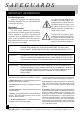
SAFEGUARDS IMPORTANT INFORMATION Product Inspection The lightning flash with arrowhead symbol, within an equilateral triangle, is intended to alert the user to the presence of uninsulated "dangerous voltage" within the product's enclosure that may be of sufficient magnitude to constitute a risk of electric shock to persons. Inspect the equipment for shipping damage. Should any damage be discovered, immediately file a claim with the carrier.
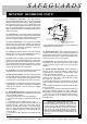
SAFEGUARDS IMPORTANT INFORMATION CONT'D 10. Grounding or Polarization - This video product is equipped with a polarized alternating - current line plug (a plug having one blade wider than the other). This plug will fit into the power socket only one way. This is a safety feature. If you are unable to insert the plug full into the outlet, try reversing the plug. If the plug should still fail to fit, contact your electrician to replace your obsolete outlet.
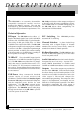
DESCRIPTIONS T he PR-3200 is an economic descrambler compatible commercial satellite receiver designed for SMATV systems. The unit has been tested by General Instruments to meet all VideoCipher® II performance requirements. The PR-3200 provides three video outputs configured to interface with all known scrambling systems. The standard 950 to 1750 MHz tuning range of the PR-3200 allows direct compatibility for international CCIR standards.
SPECIFICATIONS IF Input Video Input Impedance: ................................... 75 Ohm Impedance: ................................................ 75 ohm Input Frequency: .................... 950-1450 MHz or ...................................................... 950-1750 MHz Video Output Level: ............................ Adjustable Input Level: ................................. -30 to -60 dBm IF Frequency: ......................................... 70 MHz AFC Range: @ 70 MHz ......................
FRONT PANEL FRONT & REAR PANEL 1 2 3 3 4 5 6 7 PR-3200 SATELLITE RECEIVER .75MHz SET CATV SERIES 1. 2. 3. MODE + – 0 2 4 6 8 10 SIGNAL STRENGTH 4. SET KEY: The "SET" key is for programming the video I.F. frequency and the audio sub-carrier frequency. +/- Keys: These keys are used for changing, up or down, the channels, I.F. frequency and audio modes. C-Band 14 .25MHz MODE KEY: The "MODE" key selects the audio mode: 6.8MHz preset or 5.0MHz to 8.MHz tunable. Channel I.F. MONITOR .
REAR PANEL FRONT & REAR PANEL 8 9 10 11 12 13 14 FLAT VIDEO OUT COMP VIDEO OUT VIDEO 15 16 17 18 600VA MAX IN 950-1750 MHz INPUT 70 MHz IF LOOP OUT INV NORM 3/8 A 250V 120V 60 Hz 0.3A AUDIO FUSE LNB Power IF GAIN 19 H B/MAC V VIDCIP 20 AC ADAPTOR PLUG IN CLASS 2 TRANSFORMER UL LISTED 69NO E97199 0694 MODEL: D6-1007 INPUT:120V 60Hz 25W OUTPUT: 18VDC 250 mA 8. 9. RF Input: Input connection from C-band or Ku-band LNB. ( 950 to 1750 MHz).
INSTALLATION LNB POWERING METHODS HORIZONTAL V E R T I C A L + + + + 220VAC 50Hz 25W VERT. TO LNB HIGH OUTPUT 1 2 3 4 CAUTION 5 OUTPUTS RISK OF ELECTRIC SHOCK DO NOT OPEN HORZ.
INSTALLATION D E S C RAM B L E R & M O D U LAT O R I N T E R FAC E S PR-3200 70 MHz IF LOOP IN 950-1750 MHz INPUT OUT 600VA MAX FLAT VIDEO OUT COMP VIDEO OUT INV NORM VIDEO 120V 60 Hz 0.3A 3/8 A 250V AUDIO FUSE LNB Power H B/MAC V VIDCIP POWER 0.
PROGRAMMING 1. Plug the AC cord to an AC outlet and turn on the receiver. 2. If the receiver has not been pro-grammed for the last channel, the display shows "1" which indicates CH.1. 3. Normally, the receiver has been preset and factory programmed. See the preset Channel Table attached. 4. Select the channel number to be programmed by using "+"/"-" keys Video I.F. Frequency: 5. Start programming by pressing “SET” key. The first pressing of the “SET” key is for programming the video i.f. frequency.
PCB CONTROLS CLAMPED VIDEO ADJUST COMPOSITE VIDEO ADJUST BMAC VIDEO ADJUST 9 10 PICO MACOM INC. 12500 Foothill Blvd.
WARRANTY FIVE YEAR LIMITED WARRANTY P ico Macom, Inc. warrants to the original purchaser this product shall be free of defects in material and craftsmanship with only the limitations or exclusions set out below. During the warranty period Pico Macom Inc. or an authorized Pico Macom service facility will provide free of charge, the parts and labor necessary to correct defects in material and workmanship.
NOTES PICO MACOM INC. 12500 Foothill Blvd.
NOTES PICO MACOM INC. 12500 Foothill Blvd.
NOTES PICO MACOM INC. 12500 Foothill Blvd.
PICO MACOM INC. 12500 Foothill Blvd.