PicoScope 4000 Automotive PC Oscilloscopes User's Manual ps4000a.en-1 © Copyright 2008 Pico Technology Ltd. All rights reserved.
Contents I Contents 1 Introduction .....................................................................................................................................1 1 Overview ...........................................................................................................................................1 ...........................................................................................................................................1 2 Minimum PC requirements ...................
Introduction 1 Introduction 1.1 Overview 1 The PicoScope 4000 Series Automotive 9 Oscilloscopes are a range of high-speed PC oscilloscopes for automotive diagnostic use. They are fully USB 2.0 10 -capable and backwards-compatible with USB 1.1 10 . There is no need for an external power supply as power is supplied from the USB port, making these oscilloscopes highly portable.
2 1.3 PicoScope 4000 Series Automotive Oscilloscope User's Manual Installation instructions Important You must install the PicoScope software 9 before connecting a PicoScope 4000 Series Automotive 9 Oscilloscope to your PC for the first time. Install the software by following the steps in the quick start guide supplied with your oscilloscope. You can then connect your oscilloscope to the PC. To minimise the risk of electromagnetic interference, please use the USB 10 cable supplied.
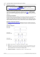
Introduction 1.4 3 Safety symbols Symbol 1: Warning Triangle This symbol indicates that a safety hazard exists on the indicated connections if you do not take correct precautions. Ensure that you read in detail all safety documentation associated with the product before using it. Symbol 2: Equipotential This symbol indicates that the outer shells of the indicated BNC connectors are all at the same potential (i.e. are shorted together).
4 1.6 PicoScope 4000 Series Automotive Oscilloscope User's Manual FCC notice This equipment has been tested and found to comply with the limits for a Class A digital device, pursuant to Part 15 of the FCC Rules. These limits are designed to provide reasonable protection against harmful interference when the equipment is operated in a commercial environment.
Introduction 1.8 5 Legal information The material contained in this release is licensed, not sold. Pico Technology grants a licence to the person who installs this software, subject to the conditions listed below. Access The licensee agrees to allow access to this software only to persons who have been informed of these conditions and agree to abide by them. Usage The software in this release is for use only with Pico products or with data collected using Pico products. Copyright Pico Technology Ltd.
6 1.9 PicoScope 4000 Series Automotive Oscilloscope User's Manual Company details Address: Pico Technology James House Colmworth Business Park St. Neots Cambridgeshire PE19 8YP United Kingdom Phone: Fax: +44 (0) 1480 396 395 +44 (0) 1480 396 296 Email: ps4000a.en Technical Support: Sales: support@picotech.com sales@picotech.com Web site: www.picoauto.com © Copyright 2008 Pico Technology Ltd. All rights reserved.
Product information 2 Product information 2.
8 PicoScope 4000 Series Automotive Oscilloscope User's Manual 3 Advanced features 3.1 Sampling modes PicoScope 4000 Series Automotive 9 Oscilloscopes run in various sampling modes. At high sampling rates, the oscilloscope collects data much faster than a PC can read it. To compensate for this, the oscilloscope stores a block of data in an internal memory buffer, delaying transfer to the PC until the required number of data points have been sampled. This is called block mode.
Glossary 4 9 Glossary AC/DC control. Each channel can be set to either AC coupling or DC coupling. With DC coupling, the voltage displayed on the screen is equal to the true voltage of the signal with respect to ground. With AC coupling, any DC component of the signal is filtered out, leaving only the variations in the signal (the AC component). Aliasing. Like all digital scopes, the PicoScope 4000 Series cannot reliably capture signals with a frequency higher than half the scope's maximum sampling rate.
10 PicoScope 4000 Series Automotive Oscilloscope User's Manual USB 1.1. USB is the abbreviation for Universal Serial Bus. This is a standard port that enables you to connect external devices to PCs. A typical USB 1.1 port supports a data transfer rate of 12 Mbps (12 megabits per second), and is much faster than a serial port. USB 2.0. USB is the abbreviation for Universal Serial Bus. This is a standard port that enables you to connect external devices to PCs. A typical USB 2.
Index Index P PC connection 7 PC Oscilloscope 1, 4, 9 PC requirements 1 PicoScope 4000 Series Automotive PicoScope software 1, 2, 9 Power supply 7 A AC coupling 8 AC/DC control 9 Accuracy 7 Analog bandwidth 1 7, 9 R B Repair 3 Resolution, vertical Block mode 8, 9 BNC connector 2 Buffer 8 Buffer size 7, 9 7, 8, 9 S Safety warning 4 Sampling rate 7, 9 Signal generator 2 Specifications 7 Spectrum analyser 1, 9 Streaming mode 8, 9 C Calibration 3 Channels 7, 8 Compliance 7 Contact details 6 T D DC
13 © Copyright 2008 Pico Technology Ltd. All rights reserved. ps4000a.
Pico Technology James House Colmworth Business Park Eaton Socon ST. NEOTS Cambridgeshire PE19 8YP United Kingdom Tel: +44 (0) 1480 396 395 Fax: +44 (0) 1480 396 296 Web: www.picotech.com ps4000a.en-1 28.10.08 © Copyright 2008 Pico Technology Ltd. All rights reserved.