Instruction Manual book ITEM CODE:BH 124 SPECIFICATION Wingspan : 2,240 mm 88.19 in. Length : 1,625 mm 63.98 in. Weight : 6,4 kg 14.08 lbs. Parts listing required (not included). Radio : 08 channels. Servo : 09 standard high torque servos. Engine : 26 - 35cc Gas. Made in Vietnam. Downloaded from www.Manualslib.
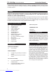
PZL-104 Wilga - Item code: BH 124 . Instruction Manual This instruction manual is designed to help you build a great flying aeroplane. Please read this manual thoroughly before starting assembly of your PZL-104 WILGA. Use the parts listing below to identify all parts. WARNING. Please be aware that this aeroplane is not a toy and if assembled or used incorrectly it is capable of causing injury to people or property. WHEN YOU FLY THIS AEROPLANE YOU ASSUME ALL RISK & RESPONSIBILITY.
PZL-104 Wilga - Item code: BH 124 . Caution: this model is not a toy! If you are a beginner to this type of powered model, please ask an experienced model flyer for help and support. If you attempt to operate the model without knowing what you are doing you could easily injure yourself or somebody else. Please keep your safety and well-being in mind at all times.
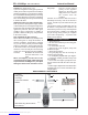
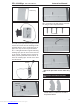
PZL-104 Wilga - Item code: BH 124 . Instruction Manual REPLACEMENT SMALL PARTS 3. 1 4. d. a. 2. b. a. b. a b c. a 6. A B. c b b. 8. c. a. 5. 7. 9. 1. Aluminium landing gear. 2. Plastic parts for landing gear. 3. Chairs 4. Pilot doll. 10. Bottom side Flap. Aileron 5. Wheels. 6. Landing gear struts 7. Tail gear set. 2. Using a modeling knife, remove the covering servo tray. 8. Plastic parts bottom fuselage. 9. Fuel Tank. 10. Plastic parts for vertical I. SERVO 1.
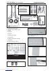
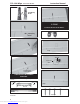
PZL-104 Wilga - Item code: BH 124 . Instruction Manual Servo tray. 5. Instal servo tray with aileron servo into the wing as same as picture below. 2x10mm. Secure. 3. Drill 1,5mm pilot holes through the block of wood for each of the four mounting screws provided with the servo. Install servo into aileron servo tray as same as picture below. 4. Using the thread as a guide and using masking tape, tape the servo lead to the end of the thread: carefully pull the thread out.
PZL-104 Wilga - Item code: BH 124 . Instruction Manual A+B Epoxy PLUS II. FLAP 1. INSTALLING THE FLAP SERVO . A+B Epoxy PLUS Flap. Thread Electric wire Control horn of the aileron 3.INSTALLING THE AILERON LINKAGES . Installing the aileron linkages as pictures below. M3 lock nut. M3. M3. Flap. 65 mm Attach the clevis to the outer hole in the control horn. 6 Downloaded from www.Manualslib.com manuals search engine 2x10mm.
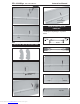
PZL-104 Wilga - Item code: BH 124 . Instruction Manual Secure. Control horn of the flap 3.INSTALLING THE FLAP LINKAGES. Installing the flap linkages as pictures below. Flap. M3 lock nut. Repeat the procedure for the other wing half. M3. M3. 65mm 2. INSTALLING THE FLAP CONTROL HORN. Control horn of the flap A+B Epoxy PLUS Bottom side Flap Aileron Top side 7 Downloaded from www.Manualslib.
PZL-104 Wilga - Item code: BH 124 . Instruction Manual 4x12mm. Drill a hole 6 mm diameter Secure Repeat the procedure for the other wing half. INSTALLING THE ENGINE MOUNT. See pictures below: 5x 90mm Secure. Engine 30cc. 8 Downloaded from www.Manualslib.
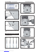
PZL-104 Wilga - Item code: BH 124 . Instruction Manual INSTALLING THE THROTTLE - CABLE. 1. Install one adjustable metal connector through the third hole out from the center of one servo arm, enlarge the hole in the servo arm using a 2mm drill bit to accommodate the servo connector. Remove the excess material from the arm. After installing the adjustable metal connector apply a small drop of thin C/A to the bottom nut. This will prevent the connector from loosening during flight.
PZL-104 Wilga - Item code: BH 124 . Instruction Manual When the stopper assembly is installed in the tank, the top of the vent tube should rest just below the top surface of the tank. It should not touch the top of the tank. 5. Test fit the stopper assembly into the tank. It may be necessary to remove some of the flashing around the tank opening using a modeling knife. If flashing is present, make sure none of it falls into the tank. Tygon gas tubing not included.
PZL-104 Wilga - Item code: BH 124 . Instruction Manual Secure. INSTALATION CHOKE SERVO. connector Choke servo Tie wrap Choke servo Electric power. Left side. Right side. 11 Downloaded from www.Manualslib.
PZL-104 Wilga - Item code: BH 124 . Instruction Manual MAIN GEAR INSTALATION. PARTS REQUIRED 1) Assemble and mounting the wheel pants as shown in the following pictures. Secure. 1. 1. 2a 2b. 2b. 6b. 6a. 6c. 5. 5. C/A glue. 4x 15mm 12 Downloaded from www.Manualslib.
PZL-104 Wilga - Item code: BH 124 . Instruction Manual Aluminium 10mm 16mm 3x25mm Landing gear struts. 3x 8mm 3x 8mm 3x 10mm 3x10mm Secure. 13 Downloaded from www.Manualslib.
PZL-104 Wilga - Item code: BH 124 . Instruction Manual 3x 25mm Secure. 3x 10mm Secure. Secure. Bottom side. Bottom side. 5x 40mm 14 Downloaded from www.Manualslib.
PZL-104 Wilga - Item code: BH 124 . Instruction Manual 10mm. cut. 30mm. Mark line cut. Push in to. Cut. h. Pus Straight lin e. 5mm 15 Downloaded from www.Manualslib.
PZL-104 Wilga - Item code: BH 124 . Instruction Manual Drill a hole 2.5mm diameter 20mm 5mm Mark point 1 Drill a hole 2.5mm diameter 5mm Mark point 2 30mm Make a tero hole drill 3mm diameter. Mark point 16 Downloaded from www.Manualslib.
PZL-104 Wilga - Item code: BH 124 . Instruction Manual Repeat the procedure for the behind side right landing gear Repeat the procedure for all left side landing gear Front view. Make a tero hole drill 3mm diameter. 3x 6mm Plastic part bottom fuselage. Secure. Secure. 17 Downloaded from www.Manualslib.
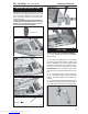
PZL-104 Wilga - Item code: BH 124 . Instruction Manual Bottom side. C/A glue. Bottom side COWLING. 1. Slide the fiberglass cowl over the engine and line up the back edge of the cowl with the marks you made on the fuselage. Top side. 2. While keeping the back edge of the cowl flush with the marks, align the front of the cowl with the crankshaft of the engine. The front of the cowl should be positioned so the crankshaft is in nearly the middle of the cowl opening.
PZL-104 Wilga - Item code: BH 124 . Instruction Manual 3. Slide the cowl back over the engine and secure it in place using three screws. See picture below. Bottom side. 4. Install the muffler and muffler extension onto the engine and make the cutout in the cowl for muffler clearance. Connect the fuel and pressure lines to the carburetor, muffler and fuel filler valve. 3 x 12mm Mark point Secure. Top side. Machine screw. Front view Drill a hole 2.5mm diameter 19 Downloaded from www.Manualslib.
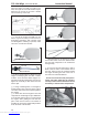
PZL-104 Wilga - Item code: BH 124 . Instruction Manual Secure. Elevator servo HORIZONTAL STABILIZER. Horizontal stabilizer installation See picture below. ELEVATOR INSTALLATION SERVO INSTALLATION 1. Install the rubber grommets and brass collets into the elevator servo. Test fit the servo into the servo tray. 2. Mount the servo to the tray using the mounting screws provided with your radio system. Elevator servo 20 Downloaded from www.Manualslib.
PZL-104 Wilga - Item code: BH 124 . Instruction Manual A+B Epoxy plus glue. 12 mm Aluminium tube. 263 mm Rudder pushpull cable. Aluminium tube. 3x 15mm. 21 Downloaded from www.Manualslib.
PZL-104 Wilga - Item code: BH 124 . Instruction Manual Secure. Bottom side. 3x 10mm ELEVATOR CONTROL HORN AND ELEVATOR PUSHROD INSTALLATION. Elevator control horn install as same as the way of aileron control horn. Please see pictures below. Control horn of Elevator. Secure A+B epoxy plus glue. A+B Epoxy Plus 22 Downloaded from www.Manualslib.
PZL-104 Wilga - Item code: BH 124 . Instruction Manual Bottom side. VERTICAL STABILIZER INSTALLATION. Rudder servo install as same as method of elevator servo. See picture below: Rudder Servo. Horizontal Stabilizer Struts. 3x 10mm 3x 10mm Elevator servo. Rudder Servo. Secure. Secure. Aluminium 23 Downloaded from www.Manualslib.
PZL-104 Wilga - Item code: BH 124 . Instruction Manual Cut. Push A+ B Epoxy Plus. RUDDER CONTROL HORN INSTALLATION. Rudder control horn install as same as the way of aileron control horn. Please see pictures below. Control horn of Rudder. Aluminium A+B Epoxy Plus. 24 Downloaded from www.Manualslib.
PZL-104 Wilga - Item code: BH 124 . Instruction Manual Plastic parts for vertical. a b Rudder control horn. c RUDDER PUSHROD INSTALLATION. Rudder pushrod install as same as the way of aileron pushrod. C/A glue. 3x 10 mm Secure Rudder pushrod. 25 Downloaded from www.Manualslib.
PZL-104 Wilga - Item code: BH 124 . Instruction Manual C/A glue. Top side. MOUNTING THE TAIL WHEEL BRACKET. 1. Set the tail wheel assembly in place on the plywood plate. The pivot point of the tail wheel wire should be even with the rudder hinge line and the tail wheel bracket should be centered on the plywood plate. 3x 15mm 2. Using a pen, mark the locations of the two mounting screws. Remove the tail wheel bracket and drill 1mm pilot holes at the locations marked. C/A glue. 26 Downloaded from www.
PZL-104 Wilga - Item code: BH 124 . Instruction Manual Servo tail gear. Secure. Servo tail gear. Cut. INSTALLING THE SWITCH. 1. Cut out the switch hole using a modeling knife. Use a 2mm drill bit and drill out the two mounting holes through the fuselage side. 2. Secure the switch in place using the two machine screws provided with the radio system. Switch Bottom side 27 Downloaded from www.Manualslib.
PZL-104 Wilga - Item code: BH 124 . Instruction Manual Battery Switch of Engine Receiver. Switch of Receiver INSTALLING THE RECEIVER AND BATTERY. 1. Plug the servo leads and the switch lead into the receiver. You may want to plug an aileron extension into the receiver to make plugging in the aileron servo lead easier when you are installing the wing . Plug the battery pack lead into the switch. INSTALLING THE COCKPIT. See pictures below: 2.
PZL-104 Wilga - Item code: BH 124 . Instruction Manual Epoxy glue. A+B Epoxy PLUS. Secure. 29 Downloaded from www.Manualslib.
PZL-104 Wilga - Item code: BH 124 . Instruction Manual 3x 10mm Secure. Secure. close. WING ATTACHMENT. Locate the aluminium wing dihedral brace. aluminium 25mm 810 mm. *** Test fit the aluminium tube dihedral brace into each wing haft. The brace should slide in easily. If not, use 220 grit sand around the edges and ends of the brace until it fits properly. 30 Downloaded from www.Manualslib.
PZL-104 Wilga - Item code: BH 124 . Instruction Manual Left wing. Right wing. Top side Secure. 3x 10mm Top side Secure 31 Downloaded from www.Manualslib.
PZL-104 Wilga - Item code: BH 124 . Instruction Manual BALANCING. CONTROL THROWS. 1) It is critical that your airplane be balanced correctly. Improper balance will cause your plane to lose control and crash. THE CENTER OF GRAVITY IS LOCATED 64MM BACK FROM THE LEADING EDGE OF THE WING. 2) Mount the wing to the fuselage. Using a couple of pieces of masking tape, place them on the top side of the wing 64mm back from the leading edge, at the fuselage sides.