OPERATING MANUAL TS - 4 Thermal Microscope Stage CONTENTS Section EB TS4 1198 Page 1.0 GENERAL DESCRIPTION 2 2.0 SETTING UP THE THERMAL MICROSCOPE STAGE 3 3.0 OPERATING INSTRUCTIONS 6 4.0 SPECIFICATIONS 7 5.
TS-4 THERMAL MICROSCOPE STAGE 1.0 GENERAL DESCRIPTION The TS-4 Thermal Microscope Stage consists of: 1.1 The STAGE, which is available in several configurations or may be custom designed. Heat is supplied to or withdrawn from the specimen by means of a thermoelectric heat pump attached to the upright portion of the controlled plate, Excess heat is conducted away by the cooling water.
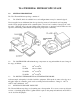
2.0 SETTING UP THE THERMAL MICROSCOPE STAGE Sections 2.1 to 2.5 describe setup of the TS-4 with a Pump and Tank Unit, PTU-3. If you are using running water from a tap, please see section 2.8. 2.1 WATER PUMP AND TANK UNIT Unscrew cap. Fill reservoir with five gallons of distilled water. DO NOT OPERATE PUMP UNLESS TANK HAS BEEN FILLED WITH WATER. PUMP MAY BE DAMAGED IF RUN DRY. AC line cord should be connected to the SWITCHED OUTLET on the rear of the controller.
2.3 ATTACH AC LINE CORD BEFORE CONNECTING CONTROLLER TO AC POWER SUPPLY, CHECK THE SETTING OF THE VOLTAGE REGULATOR MODULE This module is on the back panel, bottom left. There are four settings; 100V for unusually low power situations, 120V, 220V and 240V. Confirm the selector is set for your requirements. Slide clear plastic panel to left. If correct voltage is not visible on card, card must be pulled out and replaced so that correct voltage is visible.
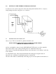
The specimen or slide is placed on the upper surface of the heat transfer plate and held in position with the stainless steel clips provided. A sensor is mounted on the rear of the stage out of the way of the slide area. A degree or two of difference between the top of the slide and the stage is normal and can be allowed for. The TS-4 stage raises the specimen 0.263” (6.7mm) above the base of the microscope.
3.0 OPERATING INSTRUCTIONS 3.1 Check that SENSOR INPUT is switched to B. The digital display will show the temperature of the stage. Depress the RUN/SET switch to SET position and hold down while adjusting the SET TEMPERATURE knob. With this 10-turn potentiometer, adjustment may be made to any temperature in the listed temperature range of the stage (See Section 1.2) Release the RUN/SET switch and allow the stage to stabilize at set temperature. This should take 1-2 minutes.
4.0 SPECIFICATIONS 4.1 CONTROLLER Operating Range: -20o to +60oC Control Accuracy: +0.1oC Digital Readout Resolution: 0.1oC Accuracy: 0.1oC, +1 digit Ambient Operating Range: 15o - 45oC Input Power Requirements: 100 - 120VAC, 60Hz, 100W 200 - 240VAC, 50Hz, 100W Safety Features: Safety shutdown with warning lamp in case of fault condition such as sensor breakage, lack of cooling water or electronics failure. Size: 8” high x 7” wide x 15” deep Weight 8 lbs.
5.0 MAINTENANCE, WARRANTY AND SERVICE 5.1 MAINTENANCE The microscope stage needs no maintenance at all. It may be cleaned as necessary with a soft cloth, water or detergent. DO NOT IMMERSE IN WATER -- because of expansion and contraction due to the wide temperature range, it is not possible to completely seal the stage. 5.2 WARRANTY. Physitemp Instruments Inc. warrants this system to be free from defects in material or workmanship for 12 months from date of shipment.