Annunciator Module SCADA 3000 ANNUNCIATOR MODULE AM-1
SCADA 3000 User’s Manual Every effort has been made to ensure that the information in this document is complete, accurate and up-to-date. Phonetics, Inc. assumes no responsibility for the results of errors beyond its control. Phonetics, Inc. also cannot guarantee that changes in equipment made by other manufacturers, and referred to in this manual, will not affect the applicability of the information in this manual. Copyright 1999 by Phonetics, Inc. First Edition, version 1.0, July, 1999.
Annunciator Module IMPORTANT SAFETY INSTRUCTIONS Your ANNUNCIATOR MODULE has been carefully designed to give you years of safe, reliable performance. As with all electrical equipment, however, there are a few basic precautions you should take to avoid hurting yourself or damaging the unit: •Read the installation and operating instructions in this manual carefully. Be sure to save it for future reference. •Read and follow all warning and instruction labels on the product itself.
SCADA 3000 User’s Manual Contents SCADA 3000 ..................................................................................................... 1 Annunciator Module ......................................................................................... 1 Important Safety Instructions ........................................................................... 3 FCC Requirements ..............................................................................................................................
Annunciator Module Introduction The SCADA 3000 Annunciator Module is an optional component for use with the SCADA 3000 system. The module provides 8 programmable LED indicators to display the status of assigned I/O points. The LEDs are bi-color (red/amber), which means that each LED is always on, thereby preventing a false reading due to a burned-out LED. Red indicates an active or ON condition and Amber indicates an inactive or OFF condition.
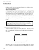
SCADA 3000 User’s Manual Installation This chapter provides information necessary to install the Annunciator Module. Correctly installing the unit will ensure proper functioning and maximum service life. Please read the entire chapter before attempting installation. OPERATING ENVIRONMENT The Annunciator Module should be mounted and operated in a clean, dry and safe environment. Do not mount the unit where it will be subject to shock and vibration.
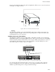
Annunciator Module the panel. Re-install the locking side panels and tighten the Allen screws to secure the enclosure to the panel. See Figure 2 below. Panel locking side panel Allen screw Rear of Module Figure 2: Rear view of mounted annunciator module Labeling The Annunciator Module comes with a blank label on the front on which you can write a description to identify each light—such as the corresponding alarm or output. We include additional blank labels for your convenience.
SCADA 3000 User’s Manual COMMUNICATIONS WIRING The Annunciator Module communicates with the SCADA 3000 using a high-speed serial communications bus. This 4-wire bus is used to connect up to 15 modules to the main unit to provide additional inputs and/or outputs. Perform all wiring with power to the main unit and modules turned off. Modules may be located a maximum of 2000' away from the main unit and should be connected in a daisy-chain fashion from one module to the next.
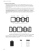
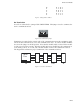
Annunciator Module 10 11 12 13 14 15 B A B A B A A A B B A A B B A A A A A A A A A A Figure 5: Setting the Bus Address Bus Termination Located on each module is a jumper labeled BUS TERM. This jumper is used to terminate the 4-wire communications bus. BUS TERM IN OUT 0 Figure 6: Bus Termination jumper Termination is required at the extreme ends of the communications network to minimize signal reflections that would otherwise cause data communication errors.
SCADA 3000 User’s Manual How the Annunciator Module Works The Annunciator module appears as an output module to the SCADA 3000. When the system is powered up, the main unit will scan the external module network and add the Annunciator to its list of modules at the address specified by the Bus Address jumpers. An icon for the Annunciator will also appear on the main unit screen.
Annunciator Module Appendix A: Specifications Network Data Rate: 153.6 Kbps Bus Termination Impedance: 120 Ohms Power Requirements: l0-l5VDC l00mA (typical) l.5W (typical) Power Fuse Rating & type: 500mA 250V, Size TR-5 (Wickmann # 3721400041) Operating temperature: 0 to 70 degrees Celsius (32 to 158 degrees F) StorageTemperature: -20 to 70 degrees Celsius (-4 to 158 degrees F) Humidity 5 to 90% non-condensing Dimensions: 3.8" x 1.85" x 5.6" Weight: 0.75 lbs.
SCADA 3000 User’s Manual Appendix B: Returning Module for Service In the event that the Annunciator Module does not function properly, we suggest that you do the following: 1) Record your observations regarding the Annunciator Module malfunction. 2) Call the Customer Service Department at (610)558-2700 prior to sending the unit to Phonetics for repair. If the module must be sent to Phonetics for Servicing, please do the following: 1) Disconnect all wiring and unplug the unit.
Annunciator Module 3 YEAR LIMITED WARRANTY 1. WARRANTOR: Dealer, Distributor, Manufacturer 2. ELEMENTS OF WARRANTY: This Product is warranted to be free from defects in materials and craftsmanship with only the limitations and exclusions set out below. 3.