
User manual


Startup and Functions
6874_en_09 PHOENIX CONTACT 3-17
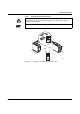
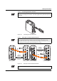
3.2.4.3 Connecting the SC-D Connectors
Figure 3-13 Connecting the SC-D connectors
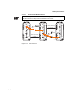
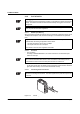
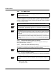
3.2.4.4 Fiber Optic Connection Between Devices
Figure 3-14 Fiber optic connection between devices
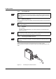
To prevent dirt from entering the connectors, do not remove the dust protection caps until
just before connecting the connectors. The same applies for the protective caps on the
connectors.
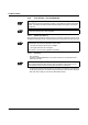
When connecting two fiber optic interface modules, note the signal direction of the fiber
optics. The fiber connection is always from the transmitter to the receiver. The
SC-D/SCRJ connectors, which are connected using a support, are keyed to ensure that
the assignment of the transmit and receive direction is correct.
6 8 7 4 0 0 2 0
6 8 7 4 0 0 2 1
3 6 0 0 0 m
( 1 1 8 1 0 0 f t . )
m a x i m u m
S i n g l e m o d e
g l a s s f i b e r
R X
R X
T X
T X
R X
T X
R X
T X
R X
R X
T X
T X
R X
T X
R X
T X
F L I F 2 F X S C - F F L I F 2 F X S C - F F L I F 2 F X S M S C - F F L I F 2 F X S M S C - F
1 0 0 0 0 m
( 3 2 8 0 8 f t . ) ,
m a x i m u m
M u l t i - m o d e
g l a s s f i b e r
The maximum length of the fiber optic cables depends on the interface module/fiber type
used.