
User manual

Assembly and Installation
6874_en_09 PHOENIX CONTACT 2-11
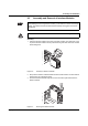
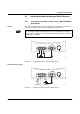
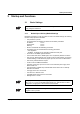
Redundant 24 V DC
supply
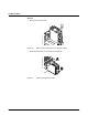
Figure 2-16 Supplying the system using two voltage sources
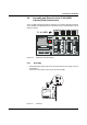
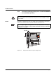
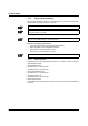
2.5.3 Alarm Contact
The switch has a floating alarm contact. An error is indicated when the contact is opened.
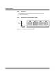
Figure 2-17 Circuit diagram for the alarm contact
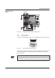
The indicated error states are configured in web-based management or via SNMP. For a
list of error states that can be configured, please refer to "Diagnostics/Alarm Contact"
Menu on page 4-36.
In the event of non-redundant power supply, the switch indicates a supply voltage failure
by opening the alarm contact. This error message can be prevented by connecting the
supply voltage to both terminals in parallel, as shown in Figure 2-13 or Figure 2-15 (for
GL), or by deactivating redundant power supply monitoring in web-based management.
U S 1
U S 2
F a i l
R e s e t
M O D E
A C T 1 0 0 F D
F L S W I T C H M M H S
O r d . N o . 2 8 3 2 3 2 6
U S 2U S 1 G N D G N D R 1 R 2
0 0 A 0 4 5 1 B D D
M A C
A d d r e s s
V . 2 4
N E F
1 - 3
2 4 V D C
-
+
N E F
1 - 3
-
+
R 1 R 2
6 7 8 4 0 0 1 5