
User manual

Assembly and Installation
6874_en_09 PHOENIX CONTACT 2-9
2.5 Installing the Modular Managed Switch System
2.5.1 Connecting the Supply Voltage to the FL SWITCH MM HS
Head Station
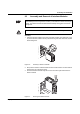
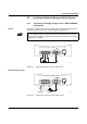
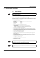
24 V DC The system is operated using a 24 V DC voltage, which is applied at the head station. If
required, the voltage can also be supplied redundantly (see Figure 2-14).
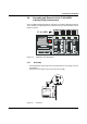
Figure 2-13 Supplying the system using one voltage source
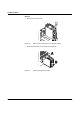
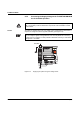
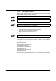
Redundant 24 V DC supply
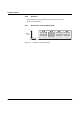
Figure 2-14 Supplying the system using two voltage sources
If redundant power supply monitoring is active (default setting), an error is indicated if
only one voltage is applied. A bridge between US1 and US2 (dotted line connection)
prevents this error message. It is also possible to deactivate monitoring in web-based
management or via SNMP.
6 8 7 4 0 0 0 5
U S 2U S 1 G N D G N D R 1 R 2
V . 2 4
2 4 V D C
X 5 X 6 X 7
2 4 V D C
6 8 7 4 0 0 0 6
2 4 V D C
U S 2U S 1 G N D G N D R 1 R 2
V . 2 4
X 5 X 6 X 7