
User manual

Assembly and Installation
6874_en_09 PHOENIX CONTACT 2-3
2.2 Assembly and Removal of Extension Modules
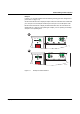
Assembly:
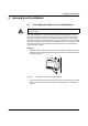
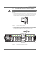
1. Place the module onto the DIN rail from above (A). The upper holding keyway must be
hooked onto the top edge of the DIN rail. Push the module from the front towards the
mounting surface (B). Check that the positive latches have snapped on properly.
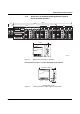
Figure 2-3 Assembly of extension modules
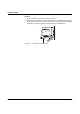
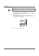
2. Now that the extension module is snapped onto the DIN rail, push it along the DIN rail
towards the head station, until the male connector/female connector of the modules
are interlatched and the sides of the modules lie flush with one another.
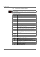
Figure 2-4 Assembly/removal of extension modules
Always switch off the supply voltage when assembling/removing the extension modules.
B
A
L N K M O D E
1
2
X 1
L N K M O D E
1
2
X 2
L N K M O D E
1
2
X 3
L N K M O D E
1
2
X 4
M o u n t i n g
R e m o v a l
6 8 7 4 0 0 0 4
U S 1
U S 2
F a i l
R e s e t
M O D E
A C T 1 0 0 F D
F L S W I T C H M M H S
O r d . N o . 2 8 3 2 3 2 6
U S 2U S 1 G N D G N D R 1 R 2
0 0 A 0 4 5 1 B D D
M A C
A d d r e s s
L N K M O D E
1
2
X 1
L N K M O D E
1
2
X 2
L N K M O D E
1
2
X 3
L N K M O D E
1
2
X 4
V . 2 4
A