
User manual

Assembly and Installation
6874_en_09 PHOENIX CONTACT 2-1
2 Assembly and Installation
2.1 Assembly and Removal of the Head Station
Mount the head station on a clean DIN rail according to DIN EN 50 022 (e.g., NS 35 ...
from Phoenix Contact). To avoid contact resistance only use clean, corrosion-free DIN
rails. Before mounting the modules, an end clamp (E/NS 35N, Order No. 08 00 88 6)
should be mounted on the left-hand side next to the head station to stop the modules from
slipping on the DIN rail. The supplied ATP-ST-TWIN side cover (see "A" in Figure 2-4) and
the end clamp should only be mounted on the right-hand side once the last extension
module has been mounted.
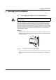
Assembly:
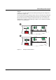
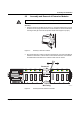
1. Place the module onto the DIN rail from above (A). The upper holding keyway must be
hooked onto the top edge of the DIN rail. Push the module from the front towards the
mounting surface (B).
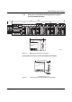
Figure 2-1 Snapping the head station onto the DIN rail
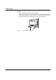
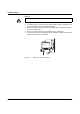
2. Once the module has been snapped on properly, check that it is fixed securely on the
DIN rail. Check whether the positive latches are facing upwards, i.e., snapped on
correctly.
Always switch off the supply voltage when assembling/removing the head station and
extension modules.
B
A