
User manual


FL SWITCH MM HS
7-8
PHOENIX CONTACT 6874_en_09
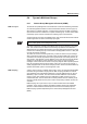
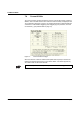
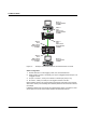
Figure 7-6 Example: Communication between termination devices via VLAN
Switch Configuration
1 Set both switches to "VLAN Tagging" mode, save, and restart devices.
2 Create VLAN 5 on switch 1 and specify port 7 as an "untagged" member and port 1 as
a "tagged" member.
3 For port 7 at switch 1, set the port VLAN ID to 5 and the port priority to any.
4 On switch 2, create port 2 and port 3 as "tagged" members of VLAN 5.
Both termination devices now communicate via the network path shown in the example
without other switch ports forwarding the broadcast packets for both termination devices,
for example.
If additional infrastructure components are located between switch 1 and switch 2, there
are two options to ensure communication between the termination devices:
LNK
MODE
1
2
X1
LNK
MODE
1
2
X2
LNK
MODE
1
2
X3
LNK
MODE
1
2
X4
US1
US2
Fail
Reset
MODE
ACT
100
FD
FL SWITCH MM HS
Ord. No.28 32 32 6
US2US1
GND GND
R1 R2
00A0451BDD
MAC
Address
V.24
FL SWITCH MCS 16TX
Ord.No. 28 32 70 0
00.A0.45.1B.D2.1D
MAC
Address
1357
2468
9
11
13
15
10
12
14
16
91610 11 12 13 14 15
18234567
MODE
ACT
100
FD
US1 US2
FAIL
X19
V.24
X17
US1 GND US2 GND
X18
R1 R2
Device B
Tagged member
of VLAN 5
Device A
Untagged member
of VLAN 5
Switch 1
Port 7
PVID 5, Prio 4
Untagged member
of VLAN 5
Switch 1
Port 1
PVID X, Prio X
Tagged member
of VLAN 5
Switch 2
Port 2
PVID X, Prio X
Tagged member
of VLAN 5
Switch 2
Port 3
PVID X, Prio X
Tagged member
of VLAN 5