
User manual

Modular Managed Switch System
6874_en_09 PHOENIX CONTACT 1-13
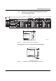
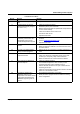
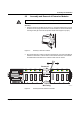
Example:
In Figure 1-11, the LED indicators have the following meaning (see also "Assignment of
ports to slots" on page 1-12):
A: The switch has been set to display the duplex mode; the mode LEDs now indicate that
port 1 and port 3 are in full duplex mode and port 2 and port 4 are in half duplex mode.
B: The switch has been set to display the data transmission rate; the mode LEDs now
indicate that port 1 and port 2 are operating at 10 Mbps, port 3 is operating at 100 Mbps,
and port 4 is not operating at all.
Figure 1-11 Example for status indicators
A C T F D1 0 0
1
2
L N K M O D E
X 1
1
2
L N K M O D E
X 2
M O D E
A
B
A C T F D1 0 0
1
2
L N K M O D E
X 1
1
2
L N K M O D E
X 2
M O D E
6 8 7 4 0 0 0 1