
User manual

FL SWITCH MM HS
1-12
PHOENIX CONTACT 6874_en_09
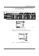
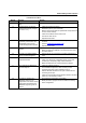
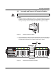
1.1.6 Assignment of Ports to Slots
Figure 1-10 Assignment of ports to slots
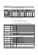
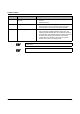
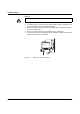
1.2 Status and Diagnostic Indicators
1.2.1 LEDs on the Head Station and Extension Modules
L N K M O D E
1
2
X 1
L N K M O D E
1
2
X 2
L N K M O D E
1
2
X 3
L N K M O D E
1
2
X 4
U S 1
U S 2
F a i l
R e s e t
M O D E
A C T 1 0 0 F D
F L S W I T C H M M H S
O r d . N o . 2 8 3 2 3 2 6
U S 2U S 1 G N D G N D R 1 R 2
0 0 A 0 4 5 1 B D D
M A C
A d d r e s s
V . 2 4
L N K M O D E
1
2
X 1
L N K M O D E
1
2
X 2
L N K M O D E
1
2
X 3
L N K M O D E
1
2
X 4
L N K M O D E
1
2
X 1
L N K M O D E
1
2
X 2
L N K M O D E
1
2
X 3
L N K M O D E
1
2
X 4
6 8 7 4 0 0 2 8
P o r t
1
P o r t
2
P o r t
3
P o r t
4
P o r t
5
P o r t
6
P o r t
7
P o r t
8
P o r t
9
P o r t
1 0
P o r t
1 1
P o r t
1 2
P o r t
1 3
P o r t
1 4
P o r t
1 5
P o r t
1 6
P o r t
1 7
P o r t
1 8
P o r t
1 9
P o r t
2 0
P o r t
2 1
P o r t
2 2
P o r t
2 3
P o r t
2 4
Des. Color Status Meaning
US1 Green ON Supply voltage 1 in the tolerance range
OFF Supply voltage 1 too low
US2 Green ON Supply voltage 2 in the tolerance range
OFF Supply voltage 2 too low
FAIL Red ON Alarm contact open, i.e., an error has occurred
OFF Alarm contact closed, i.e., an error has not occurred
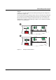
A Link LED is located above the interface module slot for each port
LNK
(Link)
Green ON Link active
OFF Link inactive
A second LED is located above the interface module slot for each port. The function of the second LED (MODE) for each
port can be set using a switch on the head station, which controls all ports (see also example below). There are three
options:
ACT
(Activity)
Green ON Sending/receiving telegrams
OFF Not sending/receiving telegrams
100 Green ON 100 Mbps
OFF 10 Mbps if Link LED is active
FD
(Duplex)
Green ON Full duplex
OFF Half duplex if Link LED is active
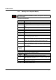
ACT and 100 and FD
simultaneously
Green
Flashing PROFINET device identification
ACT or 100 or FD
(selected by mode
switch)
Green
Flashing No IP parameter present following restart