
User manual

Modular Managed Switch System
6874_en_09 PHOENIX CONTACT 1-9
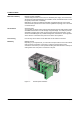
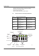
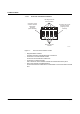
1.1.3.3 View of the Interface Modules (Example)
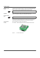
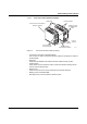
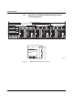
Figure 1-6 View of the interface modules (example)
– Connection for extension module/head station
This connector is used to connect the interface module and the extension module or
the head station.
– Guide bars
These bars aid installation and hold the interface modules securely in place.
– Positive latches
These latches must be pressed in order to remove the interface module (previous
versions used mounting screws).
– Ethernet ports
These are the ports for the various interfaces and connection directions.
– Marking groove for Zackband ZBF ...
– Mounting screws to lock the interface modules in place.
6 8 7 4 0 0 0 2
G u i d e b a r s
P o s i t i v e l a t c h e s
E t h e r n e t p o r t s ,
f r o n t c o n n e c t i o n
E t h e r n e t p o r t s ,
d o w n w a r d c o n n e c t i o n
C o n n e c t i o n
f o r h e a d s t a t i o n /
e x t e n s i o n m o d u l e
L a b e l i n g g r o o v e
f o r Z a c k m a r k e r
Z B F . . .
L o c k i n g
s c r e w s