
User manual

FL SWITCH MM HS
1-8
PHOENIX CONTACT 6874_en_09
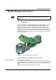
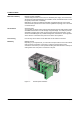
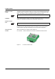
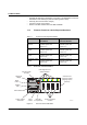
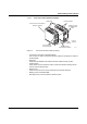
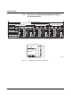
1.1.3.2 Front View of the Extension Module
Figure 1-5 Front view of the extension module
– Diagnostic/status indicators
Important information is displayed directly on the device.
– Connection for second extension module
Connect the second extension module here.
– Connection for interface modules
This is where the various interface modules are inserted and locked in place.
– Slot for first extension module/head station
Connect this extension module either to a head station or to the first extension module
here.
6 7 9 6 0 0 1 1
S l o t s f o r i n t e r f a c e
m o d u l e s
L E D d i a g n o s t i c a n d
s t a t u s i n d i c a t o r s
C o n n e c t i o n f o r s e c o n d
e x t e n s i o n m o d u l e
( o u t g o i n g s y s t e m
i n t e r f a c e )
C o n n e c t i o n f o r f i r s t
e x t e n s i o n m o d u l e /
h e a d s t a t i o n
( i n c o m i n g
s y s t e m i n t e r f a c e )
L N K M O D E
1
2
X 1
L N K M O D E
1
2
X 2
L N K M O D E
1
2
X 3
L N K M O D E
1
2
X 4