
User manual

Modular Managed Switch System
6874_en_09 PHOENIX CONTACT 1-7
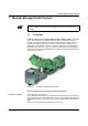
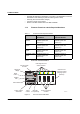
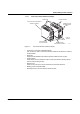
– Diagnostic/status indicators
Important information is displayed directly on the device. Each port has two LEDs. The
left-hand LED always indicates the "LINK", while the right-hand LED display is set with
the function switch.
– Function switch for LEDs
The MODE function switch can be used to specify which information is displayed by
the second port-specific LED. The three LEDs above the switch indicate the selected
mode. This information is then displayed by all port-specific LEDs (see also example
on page 1-13).
– Connection for extension module (FL MXT)
Connect the first of a maximum of two extension modules here.
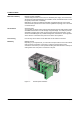
– Slots for interface modules
This is where the various interface modules (each with two ports) are inserted and
locked in place.
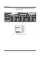
– Mini-DIN V.24 (RS-232)
V.24 (RS-232) interface in Mini-DIN format for local configuration via the serial
interface.
– Alarm contact
The floating alarm contact can be connected here via a 2-pos. COMBICON connector.
– Supply voltage connection
The supply voltage can be connected via the 4-pos. COMBICON connector
(redundancy is optional).
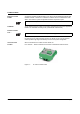
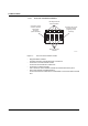
– Reset button
– Diagnostic display
Various operating states or error states can be displayed here. For a list of possible
codes, please refer to page 1-14.
In order to prevent an accidental MMS reset, the reset button must be held down for a
few seconds before it triggers a reset.