
User manual
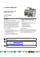


FL SWITCH SMCS 8GT
7470_en_00 PHOENIX CONTACT 8
Status and Diagnostic Indicators
IP Address Assignment
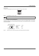
Two mechanisms are available for the assignment of the IP address: BootP or via the V.24 (RS-232) interface. By default
upon delivery, the IP address is assigned via BootP. The Factory Manager configuration software has been optimized for
use with smart managed compact switches and is the easiest way to assign the IP address. The assignment mechanism
can be modified via web-based management or via the V.24 (RS-232) interface.
Hardware Functions
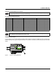
"Store and Forward" Ethernet Switching
All data telegrams that are received by the switch are saved and their validity is checked. Invalid or faulty data packets
(> 1522 bytes or CRC errors) and fragments (< 64 bytes) are rejected. Valid data telegrams are forwarded by the switch.
The switch always forwards the data using the data transmission speed that is used in the destination network segment.
Multi-Address Function
The switch independently learns the addresses for termination devices, which are connected via a port, by evaluating the
source addresses in the data telegrams. Only packets with unknown addresses, with a source address of this port or with
a multicast/broadcast address in the destination address field are forwarded via the corresponding port. The switch can
store up to 4000 addresses in its address table with an aging time of approximately 40 seconds. This is important when
more than one termination device is connected to one or more ports. In this way, several independent subnetworks can be
connected to one switch.
Des. Color Status Meaning
US1 Green ON Supply voltage 1 in the tolerance range
OFF Supply voltage 1 too low
US2 Green ON Supply voltage 2 in the tolerance range
OFF Supply voltage 2 too low
FAIL Red ON Alarm contact open, i.e., an error has occurred
OFF Alarm contact closed, i.e., an error has not occurred
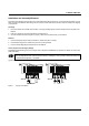
A Link LED is located on the front of the SMCS for each port
LNK
(Link)
Green ON Link active
OFF Link inactive
An additional LED is located on the front of the SMCS for each port. The function of the second LED (MODE) for each
port can be set using the MODE switch (see also example below). There are three options:
ACT
(Activity)
Green ON Sending/receiving telegrams
OFF Not sending/receiving telegrams
SPD
(Speed)
Green/
orange
ON
(orange)
1000 Mbps
ON (green) 100 Mbps
OFF 10 Mbps if Link LED is active
FD
(Duplex)
Green ON Full duplex
OFF Half duplex