
User manual


FL SWITCH SMCS 8GT
7470_en_00 PHOENIX CONTACT 7
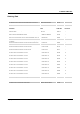
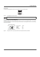
Assignment of the RJ45 Ethernet Connectors
Pin Assignment of RJ45 Connectors
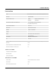
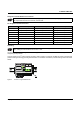
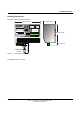
Grounding
All Factory Line devices must be grounded so that any possible interference is shielded from the data telegram and dis-
charged to ground potential.
A wire of at least 2.5 mm
2
must be used for grounding. When mounting on a DIN rail, the DIN rail must be connected with
protective earth ground using grounding terminal blocks. The module is connected to protective earth ground via the metal
header.
Figure 4 Switch on a grounded DIN rail
Please note that for operation with 1000 Mbps (Gigabit), cables with four twisted pairs (eight wires), which meet
the requirements of Cat 5 as a minimum, must be used.
Pin Number 10BASE-T/10 Mbps 100BASE-T/100 Mbps 1000BASE-T/1000 Mbps
1 TD+ (transmit) TD+ (transmit) BI_DA+ (bidirectional)
2 TD- (transmit) TD- (transmit) BI_DA- (bidirectional)
3 RD+ (receive) RD+ (receive) BI_DB+ (bidirectional)
4 - - BI_DC+ (bidirectional)
5 - - BI_DC- (bidirectional)
6 RD- (receive) RD- (receive) BI_DB- (bidirectional)
7 - - BI_DD+ (bidirectional)
8 - - BI_DD- (bidirectional)
Grounding protects people and machines against hazardous voltages. To avoid these dangers, correct instal-
lation, taking the local conditions into account, is vital.
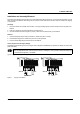
74710004
00.A0.45.06.04.02
MAC
Address
12
3
4
LINK
Mode
US2
FAIL
X9
US1 GND US2 GND
X10
R1 R2
FL SWITCH SMSC 8GT
Ord. No. 2891123
US1
X11
MEM
MODE
SPD
FD
ACT
5
6 7 8
X12
V.24
1
3
5
7
2
4
6
8