
User manual


FL SWITCH SMCS 8GT
7470_en_00 PHOENIX CONTACT 5
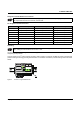
Installation and Assembly/Removal
Install the smart managed compact switch on a clean DIN rail according to EN 60715. To avoid contact resistance only use
clean, corrosion-free DIN rails. End clamps can be mounted on both sides of the module to stop the modules from slipping
on the DIN rail.
Assembly
1. Place the module onto the DIN rail from above. The upper holding keyway must be hooked onto the top edge of the
DIN rail.
2. Push the module from the front towards the mounting surface.
3. Once the module has been snapped on properly, check that it is fixed securely on the DIN rail.
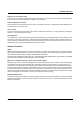
Removal
1. Pull the locking latch down using a screwdriver, needle-nose pliers or similar.
2. Pull the bottom edge of the module away from the mounting surface.
3. Pull the module diagonally upwards away from the DIN rail.
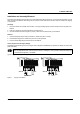
Connecting the 24 V DC Supply Voltage
The SMCS is operated using a 24 V DC voltage, which is applied via COMBICON. If required, the voltage can also be sup-
plied redundantly.
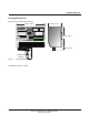
Typical supply with one (A) or two (B) voltage sources
Figure 1 Supply of the SMCS
If redundant supply voltage monitoring is active (default setting), an error is indicated if only one voltage is ap-
plied. A bridge between US1 and US2 prevents this error message. It is also possible to deactivate monitoring
in web-based management or via SNMP.
OUT
24 V DC
US1 US2
GND GNDR1R2
A
OUT
24 V DC
B
US1 US2
GND GNDR1R2
74700001