BAE HAWK JET ot <2 we SPECIFICATION Wingspan: 1750mm (68.9 in) Length: 1765mm (70 in) Flying weight: Wing area: 54 dm2 Wing loading: 180g/dm2 Gear type: Electric Retract Gear (included) with controller box (included) Servo: 2 aileron; 2 flap (Mount 21mm X 41mm) (not included) 2 elevator; 1 rudder; 1 Nose steering (Mount 17mm X 33mm) (not included) Engine: Turbine Jet Engine with thrust 8kg (not included) Gravity CG: 217 mm (8.
INSTR 1ON MANUAL pl Ie de SEE] Introduction 1 2 2 Safety precaution . 2 Important building notes. 2 Suggestion 2 Flight 2 Flight 3 Electric dusted fan recommended 3 Covering eee 3 Adhesives and required tools 3 Academy of model aeronautics national mode! aircraft safety 3 Preparations. 5 Installing the ailerons and flap 5 Installing the aileron and flap servo 6 Installing the aileron and flap 7 Installing the main landing 10 Electric retract system 12 Secure the fuselage 12 Installing the lip of air inlet..
1ON MANUAL INSTR WARRANTY Phoenix Model guarantees the component parts in this kit to be free from defects in both material and workmanship at the date of purchase by the purchaser. This warranty does not cover cosmetic damage or damage due to acts of God, accident, misuse, abuse, negligence, commercial use, or modification of or to any part of the Product. This warranty does not cover damage due to improper installation, operation, maintenance, or attempted repair by anyone other than Phoenix Model.
INSTRUCTION MANUAL * When ready to fly, first extend the transmitter aerial. * Switch on the transmitter. * Switch on the receiver. * Check that the wings are correctly fitted to the fuselage. * Operate the control sticks on the transmitter and check that the control surfaces move freely and in the CORRECT directions. © Check that the transmitter batteries have adequate power. * ALWAYS take off into the wind.
INSTRUCTION MANUAL » Free Flight fuses or devices that bum producing smoke and are securely attached to the mode! aircraft during flight. « Rocket motors (using solid propellant} up to a G-series size may be used provided they remain attached to the model during flight. Model rockets may be flown in accordance with the National Model Rocketry Safety Code but may not be launched from model aircraft.
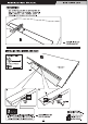
PREPARATIONS Use a covering iron with a covering sock on high heat to tighten the covering if necessary. Apply pressure over sheered areas to thoroughly bond the covering to the wood. 4 Assemble left and right A sides the same way INSTALLING THE AILERONS AND FLAPS Control hom { i < Top view > 315mm Apply instant glue B52 (CA glue, super glue). » Please note that C.A glue must be apply to these Assemble left and right = ) holes before sow th cir bof fe junior /] sides the same way.
Main Wing Flap Aileron L/] = Assemble left and right sides the same way Apply epoxy glue. Ensure smooth, non-binding movement when assembling. an. > Make certain the hinges are adequately secured with glue. If they come loose in flight accidents may result. INSTALLING THE AILERONS AND FLAPS Aileron Servo PY < Allegro Servo > €3 Cut away fim only.
1ON MANUAL 2 x 10mm TP Screw (fuss -8 = Set all screws securely. If they come off during flight you will lose control of your aircraft! {3 Tie the string. @ Pull out serve cord with string.
INSTRUCTION MANUAL AN 3x12mm N A Set all screws securely.
INSTRUCTION MANUAL 3 x 10mm Button Screw 3x12mm.
INSTRUCTION MANUAL < Top View > < Bottom View > Apply Instant glue i (CA glue, super glue).
INSTRUCTION MANUAL . Wheaties well > Apply thread locker {8 Pull out servo cord with string {screw cement).
INSTRUCTION MANUAL Front / Back Whee! (ON) AAA or Gear Door Main Whee! (O20) Navvy savvy — 2) Gear Door | Main Whee! (oN) < ELECTRIC RETRACT SYSTEM Top view Power 7.4v = = View Bottom view H Controller Box Receiver POWER 7.
5 £ Apply Instant glue {CA glue, super glue). Cut off shaded portion Open and Ei 4 Attach the wings to the fuselage and secure the wing panels.
1ON MANUAL INSTALLING THE ELEVATOR SERVO 2mm Nylon Nut Apply epoxy glue Cut off shaded portion L4] Assemble left and right "43 sides the same way
INSTRUCTION MANUAL INSTALLING THE ELEVATOR PUSH ROD ys Assemble left and right Cut off shaded portion Lg sides the same way.
INSTRUCTION MANUAL B= Assemble left and right Cut off shaded portion 2 sides the same ey
INSTRUCTION MANUAL HORIZONTAL STABILIZER INSTALLATION Cut off shaded portion Assemble left and right LA] sides the same way.
INSTRUCTION MANUAL Assemble left and right / mn sides the same way INSTALLING THE VERTICAL STABILIZER [AIE] =| » Take off the main wing after put a rudder.
INSTRUCTION MANUAL INSTALLING THE VERTICAL STABILIZER x Tom TP Soto SERVO i . Rudder Rudder £3 Cut away film only here. €) Supplied with the serve {2 Pull out servo cord with string. le] Pay close attention here! Must be purchased separately! EN... 4 Assemble left and right "43 sides the same way »Set all screws securely. If Cut off shaded portion they come off during flight you will lose control of your aircraft! 21 [ll Drill holes with the specified diameter.
INSTRUCTION MANUAL INSTALLING THE VERTICAL STABILIZER PUSH ROD Aluminum ball 2 x 10mm 2mm Nylon Nut eg 2mm Washer 40mm Aileron rod A Cut off shaded portion Assemble left and right el sides the same way
INSTRUCTION MANUAL A Set all screws securely. If they come off during flight you will lose control of your aircraft! 2x10mm 2] Apply instant glue (CA glue, super glue).
mw Apply epoxy glue Cut off shaded portion Remove the covering INSTALLING THE NOSE GEAR RETRACT Aluminum ball ©03 x 60mm Push rod 5x 45mm Cap Screw (m+ 5mm Washer eee 2 4x4mm Set Screw i : 4mm Washer eee 4 4 x 20mm Cap Screw
1ON MANUAL Aluminum bail Push rod Cut off excess. ~ ~ ELECTRIC RETRACT SYSTEM | AT) Front / Back Wheel [oes ve Top view Power 7.4v a= Cm View on view Main Wheel Tv b fvvvew H Controller Box leg) Receiver Gear Door Main Whee! POWER Note: Very important DC volt input MUST not, your system can be BROKEN. \.
WARNING it may break.
INSTRUCTION MANUAL < Trim the plastic cover > < Antenna > Cut off shaded parson Apply instant glue £1 (CA glue, super glue).
INSTRUCTION MANUAL BALANCING LATERAL BALANCE 1. It is critical that your airplane be balanced correctly. Amer you have balanced a plans on the C.G. Improper balance will cause your plane to lose control You should laterally balance it. Doing this will and crash. help the airplane track straighter. THe ENTER or GRAVITY SS al £0 217mm (8.54 1. Tum the airplane upside down. Attach one loop in s of heavy string to the engine crankshaft and AT THE FUSELAGE. BALANCE A PLANE UPSIDE one to the tail wheel wire.
INSTRUCTION MANUAL = » In order to obtain the CG specified, reposition the receiver and other equipment. IN... » If not obtain the CG specified, add a weight and adjust. » Do not fiy before confirming the Open and Close 2 correct location of the CG.
CONTROL THROWS 1. We highly recommend setting up a plane using the control throws listed. 2. The control throws should be measured at the widest point of each control surface. 3. Check to be sure the control surfaces move in the correct directions.
INSTRUCTION MANUAL 4 CHANNEL RADIO SETUP ANAL PAID Sa FLIGHT PREPARATION PRE FLIGHT CHECK bh 1. Completely charge your transmitter and receiver ©, © batteries before your first day of flying. 2. Check every Holt and every glue joint in your ELEVATOR MOVES UP RIGHTEOUSNESS LP plane to ensure that everything is tight and well bonded. ©9) 3. Double check the balance of the airplane ; 4. Check the control surface uve nar FE TOR ibe PEN 5. Check the receiver antenna .
INSTRUCTION MANUAL DECORATION < Side view > Left < Side view > Right < Top view > < Bottom view > #011 Grey #023 Ferrari Red #030Cub Yellow ~~ #071 Black #10 White