
User Manuals & Tech Notes

www.phocos.com 16 | P a g e
input are then connected to the AC source, the bus bars from the AC output are connected to the distribution panel
and loads.
PV Connections: Use the PV connection as described for individual units. Each unit must be connected to its own PV
array and must not have any electrical contact to any other units’ PV arrays.
CAUTION: Connecting a single PV array to multiple Any-Grids simultaneously will damage the Any-Grid units.
If using PV, each unit must be connected to its own individual PV array, not electrically shared with any other
units.
WARNING: Ensure all circuit breakers are open / disabled before wiring the units so that there is no voltage on
all battery, AC and PV wires.
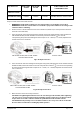
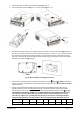
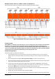
General rules for the communications connections (see Fig. 2 → ⓭ Parallel Communication Port and ⓮ Current
Sharing Port):
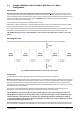
1. Every unit must have both parallel communication ports occupied. These ensure phase synchronization and
synchronization of parameters between the units.
2. Current sharing ports must only be occupied for those units where there is more than one unit on that
particular phase. If there is only one unit on a phase, then current sharing cables must not be used. These
current sharing cables ensure that all units on one phase operate at the same AC power output level.
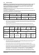
3. Every parallel communication or current sharing cable used, must either be connected directly between two
neighboring units, or with a maximum of one unit between them.
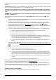
4. Connecting parallel communication cables, assuming units are numbered from 1 to ≤ 9 from left to right:
a) Connect the left black parallel communication port of unit 1 to the right port on unit 2.
b) Connect the right port of unit 1 to the left port of unit 3.
c) Connect the left port of unit 2 to the to the right port of unit 4.
d) Continue connecting the right port of each odd-numbered unit to the left port of the next odd-
numbered unit. Continue connecting the left port of each even-numbered to the right port of the
next even-numbered unit, until there are only two unoccupied black ports.
e) Connect the unoccupied black port of the last unit to the unoccupied black port of the second-to-
last unit.
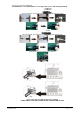
5. Connecting current sharing cables just like step 4, assuming units are numbered from 1 to ≤ 9 from left to
right on a particular phase (there must be no connection of current sharing cables between any two phases’
units!):
a) Connect the left green current sharing port of unit 1 to the right port on unit 2.
b) Connect the right port of unit 1 to the left port of unit 3.
c) Connect the left port of unit 2 to the to the right port of unit 4.
d) Continue connecting the right port of each odd-numbered unit to the left port of the next odd-
numbered unit. Continue connecting the left port of each even-numbered to the right port of the
next even-numbered unit, until there are only two unoccupied green ports on the particular phase.
e) Connect the unoccupied green port of the last unit to the unoccupied green port of the second-to-
last unit.
f) Repeat steps 5a to 5e for further phases with more than one unit.
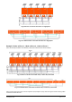
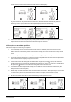
The following section will show a few examples of how the parallel communication and current sharing cables are
mounted. For better visibility download this manual in color at www.phocos.com.
Once commissioning is completed, the following settings menus (see chapter “Device Operation Settings”) are
automatically synchronized between all units: 01, 02, 03, 05, 06, 07, 08, 09, 10, 12, 13, 23, 26, 27, 29, 30, 32, 33, 34, 35,
36, 37, 39 and 41. All settings not mentioned here, and priority timers, can be set on each unit individually.
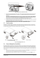
Example: 5 Units on Single Phase
Note: this example excludes circuit breakers, SPDs, RCDs and bus bars for better visibility.