
User Manuals & Tech Notes

www.phocos.com 14 | P a g e
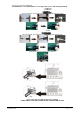
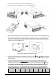
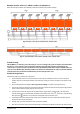
3. Remove the cable connected to the display module (Fig. 11 → ③).
4. Screw the bracket removed in Fig. 11 → ① back in place (Fig. 11 → ④).
Fig. 11: Remote display removal
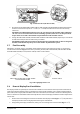
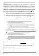
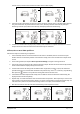
5. Drill the three mounting holes in the marked distances of 70 mm, 2.76 in into each other (Fig. 12, left). Use
M3, size no. 4 diameter screws. The screw heads must be between 5 ~ 7 mm, 0.2 ~ 0.3 in. Screw the bottom
two screws into the wall where the display module is to be mounted and let the screw heads protrude 2
mm, 0.08 in. from the wall. Slide the display down on the protruding screw heads. Now insert and tighten
the third screw at the top (Fig. 12, right).
Fig. 12: Remote display mounting hole locations
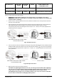
6. Install one end of the Ethernet patch cable (not included) into socket (Fig. 2, top right) on the display
module (right side). Install the other end of the Ethernet patch cable into socket (Fig. 2, bottom left) on
the Any-Grid unit.
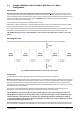
7. If using Lithium batteries designed for battery management system (BMS) communication such as
Pylontech batteries, please visit www.phocos.com for a current list of batteries supported with BMS
communication. Connect the special battery BMS cable (ask your dealer for details) to socket (Fig. 2).
CAUTION: Ensure the battery and BMS is compatible with the Any-Grid and that the pin location is
correct before connection. Damage to any communication port or the battery due to incorrect
connection or cables is not covered by warranty. Do not use any inverter communication cables
included with your battery, consult your Phocos dealer for appropriate Any-Grid cables instead.
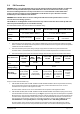
Pin (see Fig. 2)
1
2
3
4
5
6
7
8
Function
RS-232 RX
RS-232 TX
RS-485 B
+12 Vdc
RS-485 A
CAN H
CAN L
GND
Remove
Push
Pull
Screw in