
User Manuals & Tech Notes

www.phocos.com 11 | P a g e
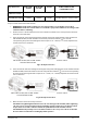
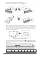
5.6 PV Connection
WARNING: Before connecting the PV module array to the PV input of the Any-Grid, install a DC circuit breaker
between each Any-Grid PV terminal pair and the PV modules. This ensures the inverter can be securely
disconnected during maintenance and is protected from over-current of the PV modules. PV modules
produce a dangerous voltage even at low light. Make sure the breaker is open / off for the rest of the
installation procedure until instructed otherwise.
WARNING: Ensure the PV cables are sized according to the table below. Inadequate PV cables can cause
excessive heat or fire during operation.
CAUTION: Short-circuiting the PV+ to the PV- terminal or any of these terminals to the metal body of the unit
will cause permanent damage not covered under warranty.
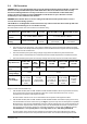
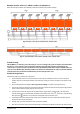
Recommended PV cable cross-section and DC circuit breaker rating:
Any-Grid model
PSW-H-5KW-230/48V
PSW-H-3KW-230/24V
PSW-H-3KW-
120/24V
PSW-H-5KW-120/48V
PSW-H-6.5KW-120/48V
PSW-H-8KW-230/48V
PV cable cross-
section
2.5 ~ 16 mm², AWG 5 ~ AWG 13
4 ~ 6 mm², AWG 10 ~ AWG 12
Circuit breaker
rating
30 Adc, min. 450 Vdc
30 Adc, min.
250 Vdc
25 Adc, min. 250 Vdc
per PV input
30 ~ 35 Adc,
min. 500 Vdc
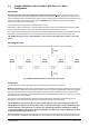
For selecting the correct PV module configuration, please consider the following points:
• The total open circuit voltage (Uoc / Voc) of the PV module array may never exceed the values in the table
below. Consider the coldest possible temperatures at the installation location together with the temperature
coefficient of the PV modules used.
• The total maximum power point voltage (Umpp / Vmpp) of the PV module array must be above the
minimum values in the table below. Consider the hottest PV module temperatures at installation location.
• The total maximum power point current (Impp / Ampp) of the PV array may not exceed the values below.
Any-Grid model
PSW-H-8KW-
230/48V
PSW-H-
5KW-
230/48V
PSW-H-
3KW-
230/24V
PSW-H-5KW-
120/48V
PSW-H-6.5KW-
120/48V
PSW-H-3KW-
120/24V
Max. PV voltage
(Uoc)
500 Vdc
450 Vdc
250 Vdc
Min. PV mpp
voltage (Umpp)
120 Vdc
90 Vdc
Max. mpp
current (Impp)
30 Adc (up to
27 Adc usable)
per input, 40
Adc total max.
usable
27.5 Adc
(up to 22 Adc
actually usable)
27.5 Adc (up to
22 Adc usable)
per input, 30
Adc total max.
usable
27.5 Adc (up to
22 Adc usable)
per input, 36
Adc total max.
usable
27.5 Adc (up
to 22 Adc
actually
usable)
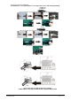
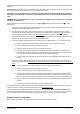
Steps to connect the PV module array:
1. PSW-H-5KW-120/48V, PSW-H-6.5KW-120/48V and PSW-H-8KW-230/48V: if the PV array has MC4 connectors,
do not remove them. If the array has different connectors, cut them off and remove 8 mm / 0.3 in of
insulation from the positive and negative PV cables.
All other models: remove 10 mm / 0.4 in of insulation from the positive and negative PV cables.
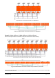
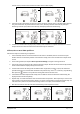
2. PSW-H-5KW-120/48V, PSW-H-6.5KW-120/48V and PSW-H-8KW-230/48V: use an MC4 crimping tool to crimp
the included MC4 connectors to the PV array (see Fig. 9.1, top) if the array does not already have compatible
MC4 connectors.
Only use the included MC4 connectors if the PV cable has the cross-section outlined in the
first table of this chapter
. Double-check polarity. Then insert the finished MC4 connectors into the PV1 and
PV2 connectors on the inverter, positive (+) on the left and negative (-) on the right (see Fig. 9.1, bottom).
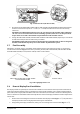
CAUTION: Ensure correct polarity before connecting. Failure to do so will damage the PSW-H.
All other models: insert the two PV wires through the rectangular casing hole (cable glands for 120 Vac
models) marked “PV input”. Insert the positive PV cable into the “PV+” terminal and the negative PV cable