Philips CM12 (S)TEM Alignment & Setup Manual
Erwin Sabio Philips CM12 Alignment & Setup Manual Page 2
Erwin Sabio Philips CM12 Alignment & Setup Manual Page 3 Table of Contents Parts of the CM12 The Microscope The Control Panels The Specimen Holder The Side Entry Specimen Chamber 4 Start-up Procedure Powering up the Microscope Saturating the Filament 7 Column Alignment Centering the Beam Alignment of Thermionic Gun Condenser Aperture Adjustment Condenser Astigmatism Correction 9 Sample Loading and Unloading Mounting the Specimen Inserting the Specimen Holder Sample Image Adjustment Optimizing Euce
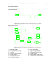
Erwin Sabio Philips CM12 Alignment & Setup Manual Page 4 Parts of the CM12 The Microscope 1 2 4 3 5 6 8 7 Figure 1 The Philips CM12 (S)TEM Microscope 1 Electron Gun 2 6 7 Condenser Aperture Assembly Specimen Chamber/Holder Objective Aperture Assembly Field Limiting Aperture Assembly Binoculars Viewing Window 8 Mechanical Stage Controls 3 4 5 A filament tip (LaB6 in this case) that emits electrons upon application of electrical current.
Erwin Sabio Philips CM12 Alignment & Setup Manual Page 5 The Control Panels Left Control Panel 10 9 Figure 2 The Control Panel located to the left of the microscope column. Right Control Panel 16 11 12 17 4 13 18 19 14 15 20 21 Figure 3 The main control panel on the right hand side of the microscope.
Erwin Sabio Philips CM12 Alignment & Setup Manual Page 6 The Specimen Holder 23 24 22 Figure 4 The CM12 Specimen Holder 22 Black Cap 23 O-ring 24 Specimen Cavity & Clamp The Side Entry Specimen Chamber 25 27 26 28 Figure 5 The Side Entry Chamber 25 Tilt Knob 26 Indicator Light Startup Procedure 27 28 Z-Adjustment Knob Tilt Lock Lever
Erwin Sabio Philips CM12 Alignment & Setup Manual Page 7 Powering Up the Microscope 1. Start by logging in to the computer connected to the TEM. Login is a necessary step to prevent unauthorized users from accessing the microscope. Without login, the control panel is not accessible. 2. Turn on the control panel by pushing the Power Switch [13] on the left hand side of the screen. 3. At this point, the main menu will appear on the computer screen.
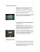
Erwin Sabio Philips CM12 Alignment & Setup Manual Page 8 3. Start saturating the filament by slowly turning the Filament Knob [18] clockwise. Each click raises the level by one with a wait time of 5 seconds between each step. 4. As the filament saturation is being adjusted, check the green beam on the large screen inside the viewing chamber [7]. The brightness of this beam indicates the relative intensity of the actual electron beam. Turn the filament knob to reach just enough brightness of the beam.
Erwin Sabio Philips CM12 Alignment & Setup Manual Page 9 Column Alignment Centering the Beam 1. To center the beam more easily, adjust the intensity knob [9] to find the cross over i.e. the brightest and more focused beam setting. (Note: if the intensity knob is a little hard to control, press the FINE button [10] to spread or concentrate the beam more slowly.) 2. Check to see if the center of the beam coincides with the black dot on the screen. 3. Use the X & Y shift knobs [15] to center the beam.
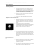
Erwin Sabio Philips CM12 Alignment & Setup Manual Page 10 Condenser Aperture Adjustment 1. The condenser aperture controls the beam that passes through the condenser lens. If the aperture is not aligned, the beam will not spread concentrically on either side of the cross-over when the intensity knob is turned. Start aligning by spreading the beam on one direction past the crossover. Figure 11 A non-concentric beam is seen when the condenser aperture is not aligned. 2.
Erwin Sabio Philips CM12 Alignment & Setup Manual Page 11 Sample Loading & Unloading Mounting the Sample Figure 13 An example of a TEM grid used to hold thin film samples 1. Samples for the CM12 are deposited as thin films on a copper mesh grid such as in Figure 13. This grid is the one loaded into the specimen holder (Figure 4) by first lifting the specimen clamp [24] using a pin-looking tool. (Note: Care must be taken to lift the clamp very gently so as not to break the fragile contraption.
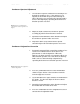
Erwin Sabio Philips CM12 Alignment & Setup Manual Page 12 Sample Image Adjustment-Optimizing Eucentric (Z) Height 1. Adjust the beam intensity on the sample or increase the magnification by turning the magnification knob [14] to see certain structures of the sample. Then pick a feature on the center of the sample as a reference point for adjusting the Z-height. Figure 14 The center of the four holes in this sample can be chosen as a reference point for z-height adjustment. 2.
Erwin Sabio Philips CM12 Alignment & Setup Manual Page 13 5. Once rotation center has been aligned, press ALGN to exit the current mode. Sample Image Adjustment-Centering the Pivot Point 1. Adjusting the pivot point ensures that the beam of electrons coincide in one spot. To start, go to the crossover of the beam. 2. Press the ALGN button then select PIVOT PT X from the onscreen menu. If the beam splits into two, then the pivot point needs to be aligned.
Erwin Sabio Philips CM12 Alignment & Setup Manual Page 14 Obtaining the Image Fine Tuning the Microscope 1. Use the mechanical stage controls to select certain areas of the sample to be captured. 2. Increase the magnification and adjust the focus knobs as necessary to see textures and fine features of the sample. 3. Use the binoculars [6] and small viewing screen as necessary to look at desired areas of the sample. Capturing the Image 1.
Erwin Sabio Philips CM12 Alignment & Setup Manual Page 15 Power Down Sequence 1. Return the viewing screen back to its original position and spread the beam. 2. If high magnification was used, lower the magnification to about 7100x by moving the magnification knob counter-clockwise. 3. Go to MODE > CONFIGURATION then turn the filament knob counter-clockwise until the filament level goes back to zero. (Note: There is no wait time when decreasing the filament saturation. 4.
Erwin Sabio Philips CM12 Alignment & Setup Manual Page 16 Photo Credits Figure # 1 2 3 4 5 6 7 8 9 10 11 12 13 14 15 16 Source Mehraeen S. (2007, January 19). 230L, first report. Email attachment. Browning, Nigel (2006). 1Experiment. p. 4, EMS 230L Internal Presentation. Ibid. Ibid. Mehraeen S. (2007, January 19). 230L, first report. Email attachment. Author’s photo Ibid. Ibid. Williams, David B. and Carter, C. Barry (1996). Transmission Electron Microscopy. (Volume I, p. 74). New York: Plenum Press.