
Switch User Manual
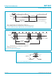
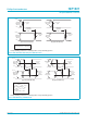
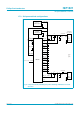
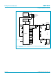
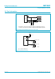
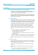
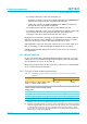
Table Of Contents
- 1. General description
- 2. Features
- 3. Applications
- 4. Abbreviations
- 5. Ordering information
- 6. Block diagram
- 7. Pinning information
- 8. Functional description
- 9. Configuration selections
- 10. Hub controller description
- 11. Descriptors
- 12. Hub requests
- 13. Limiting values
- 14. Recommended operating conditions
- 15. Static characteristics
- 16. Dynamic characteristics
- 17. Application information
- 18. Test information
- 19. Package outline
- 20. Soldering
- 21. Revision history
- 22. Data sheet status
- 23. Definitions
- 24. Disclaimers
- 25. Licenses
- 26. Trademarks

Philips Semiconductors
ISP1521
Hi-Speed USB hub controller
Product data Rev. 03 — 24 November 2004 47 of 53
9397 750 13702
© Koninklijke Philips Electronics N.V. 2004. All rights reserved.
18. Test information
(1) Transmitter: connected to 50 Ω inputs of a high-speed differential oscilloscope.
Receiver: connected to 50 Ω outputs of a high-speed differential data generator.
Fig 21. High-speed transmitter and receiver test circuit.
(1) C
L
= 50 pF for full-speed.
Fig 22. Full-speed test circuit.
mdb273
DMn
DPn
50 Ω coax
50 Ω coax
DUT
GND
V
CC
143 Ω
15.8 Ω
15.8 Ω
143 Ω
(1)
D−
D+
C
L
(1)
(1)
15 kΩ
DPn
DMn
RPU
3.3 V
1.5 kΩ ± 5%
DUT
mdb274
C
L
(1)
15 kΩ
test point
full-
speed
test point