
Switch User Manual
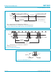
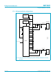
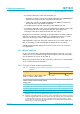
Table Of Contents
- 1. General description
- 2. Features
- 3. Applications
- 4. Abbreviations
- 5. Ordering information
- 6. Block diagram
- 7. Pinning information
- 8. Functional description
- 9. Configuration selections
- 10. Hub controller description
- 11. Descriptors
- 12. Hub requests
- 13. Limiting values
- 14. Recommended operating conditions
- 15. Static characteristics
- 16. Dynamic characteristics
- 17. Application information
- 18. Test information
- 19. Package outline
- 20. Soldering
- 21. Revision history
- 22. Data sheet status
- 23. Definitions
- 24. Disclaimers
- 25. Licenses
- 26. Trademarks

Philips Semiconductors
ISP1521
Hi-Speed USB hub controller
Product data Rev. 03 — 24 November 2004 46 of 53
9397 750 13702
© Koninklijke Philips Electronics N.V. 2004. All rights reserved.
Fig 20. Self-powered hub; ganged port power switching; global overcurrent
detection.
PSW1_N
TEST_HIGH
OC1_N
5.1 V ± 3 %
POWER SUPPLY
(kick-up)
−
+
1
V
BUS
D+
D−
GND
port 2
to
port 6
SHIELD
+4.75 V
(min)
+4.95 V (min)
V
REF(5V0)
GND
ISP1521
120 µF
ferrite bead
downstream
port connector
T1
0.1 µF
47 kΩ
004aaa306
V
CC
ADOC
7
V
BUS
D+
D−
GND
SHIELD
+4.75 V
(min)
120 µF
ferrite bead
low-ohmic
sense resistor
for overcurrent
detection
OC2_N
OC3_N
OC4_N
OC5_N
OC6_N
OC7_N
+ 5 V
PSW3_N
PSW2_N
PSW4_N
PSW5_N
PSW6_N
PSW7_N
TEST_LOW
3.3 V LDO
VOLTAGE
REGULATOR
3.3 V or 5.0 V