
Switch User Manual
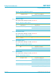
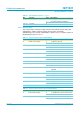
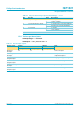
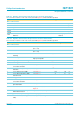
Table Of Contents
- 1. General description
- 2. Features
- 3. Applications
- 4. Abbreviations
- 5. Ordering information
- 6. Block diagram
- 7. Pinning information
- 8. Functional description
- 9. Configuration selections
- 10. Hub controller description
- 11. Descriptors
- 12. Hub requests
- 13. Limiting values
- 14. Recommended operating conditions
- 15. Static characteristics
- 16. Dynamic characteristics
- 17. Application information
- 18. Test information
- 19. Package outline
- 20. Soldering
- 21. Revision history
- 22. Data sheet status
- 23. Definitions
- 24. Disclaimers
- 25. Licenses
- 26. Trademarks

Philips Semiconductors
ISP1521
Hi-Speed USB hub controller
Product data Rev. 03 — 24 November 2004 37 of 53
9397 750 13702
© Koninklijke Philips Electronics N.V. 2004. All rights reserved.
[1] For minimum value, the HS termination resistor is disabled and the pull-up resistor is connected. Only during reset, when both the hub
and the device are capable of high-speed operation.
[2] Characterized only, not tested. Limits guaranteed by design.
[3] In the suspend mode, the minimum voltage is 2.7 V.
Resistance
Z
INP
input impedance 10 - - MΩ
Termination
V
TERM
termination voltage for pull-up
resistor on pin RPU
[3]
3.0 - 3.6 V
Table 39: Static characteristics: USB interface block (DP0 to DP7 and DM0 to DM7)
…continued
V
CC
= 3.0 V to 3.6 V; T
amb
=
−
40
°
Cto+70
°
C; unless otherwise specified.
Symbol Parameter Conditions Min Typ Max Unit