See page 10 for quick start Ethernet Converter Device FMod-TCP BOX User Manual Version 1.
/ 58 Version: 1.2 Last revision: August 14th, 2006 Printed in Switzerland © Copyright 2003-2006 FiveCo Sàrl. All rights reserved. The contents of this manual may be modified by FiveCo without any warning. Trademarks Windows® is a registered trademark of Microsoft Corporation. Ethernet® is a registered trademark of Xerox Corporation. Java® is a registered trademark of Sun Microsystem. Philips® is a registered trademark of Koninklijke Philips Electronics N.V.
/ 58 Table of Contents 1 Package and operating conditions .................................................................................................................5 Starter Kit contents ................................................................................................................................................5 Absolute maximum rating..................................................................................................................................5 2 Overview....
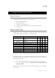
/ 58 Revision history Revision Date Author 1.0 1.1 05.05.06 09.06.06 AG AG 1.2 14.08.06 AG Note - First version - Update specifications - Text corrections - I2C speed correction. - Warning register bits correction. Firmware version Since 1.0 Since 1.0 Applet version Since 1.0 Since 1.0 Win32 app version Since 3.0 Since 3.0 Since 1.0 Since 1.0 Since 3.0 FMod-TCP User Manual v.2.
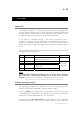
/ 58 1 Package and operating conditions Starter Kit contents The FMod-TCP BOX “Starter kit” should contain: FMod-TCP BOX device RS232 DSub cable DIN 41651 40 lines cable CD-Rom with dedicated software and Java applet sample This manual Absolute maximum rating Damage may occur if the device is operated using values beyond those mentioned below; device operation is not guaranteed.
/ 58 2 Overview Applications The FMod-TCP BOX is a TCP/IP server that allows system integrators to connect different devices such as home appliances, industrial sensors and industrial control systems directly to the Ethernet network, (10BaseT) and to remotely monitor and control those using standard protocols. It can either be accessed through a TCP socket connection, from a computer, or through a simple Web Page in a standard browser which can be directly loaded to the device (max 44kb).
/ 58 "Question & Answer" oriented. The PC should send a Question, wait for the Answer and so on. To configure the device's parameters and to access I/O and A/D features, the protocol uses an Internal Registers Access routine (see chapter 4 and 7). The code samples available on the FiveCo's web site can help programmers get started with development.
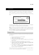
/ 58 See page 9 to know how the SOS button works. Two LEDs illuminate the SOS button and the displayed color as the following meanings: Green Red Red-Green blinking Everything is normal. There is an error. See Warning register to know the source of the error. The device found another one with the same IP address on the network. Disable the other device and reboot the FMod-TCP BOX.
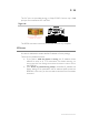
/ 58 The I2C pins are provided through a Philips PCA9512 driver chip. 10kΩ pull-ups are connected to SCL and SDA. Right side Standard RS232 DSub 9 connector (male like on a computer) 1 2 3 4 5 NC Receive data Transmit data NC GND 6 7 8 9 NC Request To Send Clear To Send NC The RS232 connector is the same as the ones found on any computer. SOS button A button is dedicated to restore default IP address or factory settings.
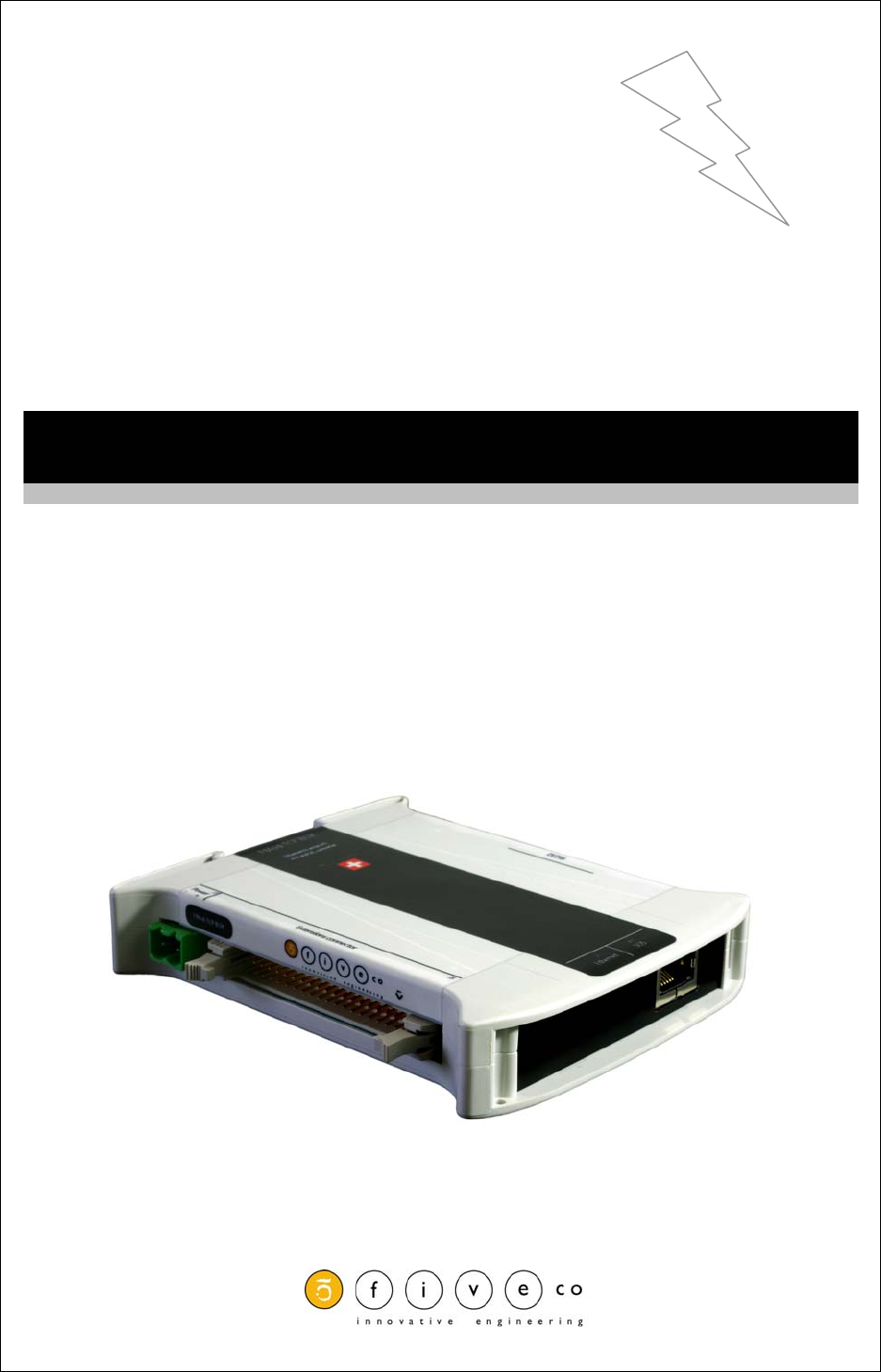
/ 58 3 Quick start This section is intended to help users to quickly plug the module into their system and establish a connection between the computer and the device. You can find the device’s factory communication settings on the following label. FMOD-TCP BOX INPUT(supply) : 5-32V DC, max 3A MAC: 00-50-C2-30-xx-xx / IP : 169.254.5.5 This device is not intended to be used in a medical, life-support or space product.
/ 58 You can now connect the device with the Win32 software or open its web page by typing its new IP address into a web browser. Notes: The IP address won't be changed if a TCP connection exists with the device. The protocol used to change the IP address is described later in this manual. FMod-TCP User Manual v.2.
/ 58 4 Controlling the FMod-TCP BOX by TCP or UDP General Information All the device's parameters (configuration registers) and features can be accessed through a TCP or UDP port. In addition, an HTTP-TCP port is available for web pages downloading and another TCP port for RS232 bus access. Those ports are: TCP Port #80 for HTTP communication. TCP Port #8000 for RS232 transceiver. TCP Port #8010 to access I/O registers (see chapter 7) and I2C bus.
/ 58 So, with speeds greater than 9600bds, the buffer may be filled faster than data can be sent by TCP and part of those will be lost if no RS232 hardware flow control is used between the FMod-TCP BOX and the RS232 device (CTS and RTS lines). If you cannot use hardware flow control on RS232 bus and you have to get more than 2048 bytes at one time, the solution is to reduce the TCP acknowledgement delay on your computer. For WindowsTM 2000/XP users, you can add/change the following value in the registry.
/ 58 Registers access feature TCP/IP works in big endian: most significant byte first, followed by least significant byte. The access to the data is done through an easy (6 byte header) protocol over TCP. Structure of each packet: 1. 2. 3. 4. 5. Function ID (2 bytes), Transaction ID (2 bytes) Length of the parameters (2 bytes) Parameters (X byte) Checksum (2 bytes) (described later in this chapter) The user (sender) defines the values of the Transaction IDs himself.
/ 58 Write register(s) command: Byte# 0x00 0x02 0x04 Write (0x0022) TransactionID Number of bytes in command Register Addresses Register value 0x06 0x07 Number of bits Example 16 bits 16 bits 16 bits 0x0022 0x1B34 0x0003 8 bits 8 — 64 bits 0x02 0x1234 The two previous entries are replicated for every register that has been asked for reading … Checksum 16 bits 0x… The max length of this sequence is 180 bytes.
/ 58 To be able to do all of these 3 sequences, use this command: Byte# 0x00 0x02 0x04 0x06 0x07 0x08 …. I2CRWwithAck (0x0007) TransactionID LengthOfParameters (X + 3) 7 bits Address (bit 7 = 0) X (number of bytes to write) xBytes Y (number of bytes to read) Number of bits Example 16 bits 16 bits 16 bits 8 bits 8 bits X bytes 8 bits 0x0007 0x1B34 0x0005 0x28 0x02 0xAF1D 0x05 The four previous entries can be replicated to access the same or other I2C slaves within this command sequence.
/ 58 Note that the max length of those sequences is 180 bytes. Pay close attention to building sequences that do not exceed this and not to ask too much byte in answer ! The FMod-TCP BOX translates automatically those sequences to I2C sequences. It is mandatory that the sequence has to be transmitted within one TCP packet. Otherwise, the FMod-TCP BOX will ignore it. I2C Bus scanning The following command allows user to ask an I2C bus scanning to list which addresses answer with an acknowledge.
/ 58 3. The I2C controller does not match all I2C specifications at speed higher than 100kHz. This feature will therefore not work with all I2C slaves. The value of the I2CSPD parameter must be computed with the following formula: I 2CSPD = 107 −1 I 2CSpeed wanted The I2C speed cannot be saved in EEPROM. FMod-TCP User Manual v.2.
/ 58 Easy IP address config (UDP # 7010) A really useful feature of the UDP port #7010 is the "Easy IP config" one. The user who wants to design his own software can use this feature to do a "quick start/install" method. Indeed, since this protocol uses a broadcast UDP packet, even if the device is not in the same subnet, it should receive its new IP address and subnet mask.
/ 58 Checksum calculation This checksum is the same as the IP checksum. Definition: sum of 1’s complement of all 16 bits words of whole message (FiveCo packet) except checksum bytes. Note: all values are unsigned! Sequence: 1. Clear accumulator Loop x. Only if last word is not made of two bytes, the data byte is the upper byte (big endian) 2. Compute 1’s complement of each 16bits word, result is 16bits 3. Convert last result from 16 bits to 32 bits, result is 32bits: 0x0000+last result 4.
/ 58 Here is an example of a checksum calculation function in C: int RetCheckSum(Byte* ByteTab, int Size) { // This function returns the calculated checksum unsigned int Sum=0; bool AddHighByte=true; unsigned int ChecksumCalculated; for(int i=0;i>16)&0xFFFF)+(Sum&0xFFFF); ChecksumCalculated = ((ChecksumCalc
/ 58 5 Java A pplet A specific Java Applet is provided with the module to control any of its ports without having to write any specific code. Overview To connect to the http server on the device, simply open your web browser and type the IP address of the module. Example with default address: “http://169.254.5.5” The applet is downloaded from the device to your computer and runs as a local process (on your computer). You need to use an internet web browser that is compatible with Java 1.1.
/ 58 Main Config The Main panel shows the general information related to the device. • The first part allows the user to change the main settings of the device. Don't forget to use the "Save user parameters" button to make changes permanent! • The second part allows the user to save/restore user and factory parameters and to read the actual configuration of the device if it has been modified by another application. FMod-TCP User Manual v.2.
/ 58 Test A/D and I/Os This page can be used to access Inputs state and voltage and change Outputs state. The Inputs state and voltage are regularly updated automatically (20 kHz). You can change the low to high threshold of the inputs between 0 and 24V. This page display also the device supply voltage and warnings (Too low/high supply voltage, Outputs driver over current or temperature). FMod-TCP User Manual v.2.
/ 58 Test RS232 This page can be used to access RS232 bus. If you click on the "Connect to RS232 TCP Port" you can send ASCII data to RS232 bus and receive data from it (only ASCII is visible in this application). You can check "Add LF", "Add CR" and/or "Add Null" boxes to add a Line Feed, a Carriage Return and/or a Null Byte at the end of the ASCII chain sent to the device. FMod-TCP User Manual v.2.
/ 58 Test I2C This page can be used to access I2C bus. The panel is divided in two parts: The part on the right allows scanning the I2C bus to find available slave devices. The part on the left allows sending a read or a write command to a device on the I2C bus. You should first check if you want a read or a write. Then you have to write hex data to write to the device in the "Hex data to write" field (if you FMod-TCP User Manual v.2.
/ 58 checked the "Read" box, the FMod-TCP BOX will use the read after write I2C feature). After writing the I2C address (7bits hexa) and the number of bytes to read (if applicable), click on the "Send" button. The answer is displayed in hex in the "Data received" field. FMod-TCP User Manual v.2.
/ 58 6 Win32 A pplication A specific application is provided with the module to control any of its ports without having to write a specific code. Overview IP address of the module Open or close TCP port TCP port number Depends on port Connection status To open a TCP port on the module, the user has to set the correct IP address of the module, to choose the correct TCP port in the list and to click on the "Open" button. To close the port, simply click on the "Close" button.
/ 58 This application uses the IP address of your computer and its subnet mask to find the scan broadcast address. When you click on scan, a broadcast message will be sent to all devices in your subnet and answers will be listed. WARNING: it only works with devices in your subnet! How does it work? When you click "Scan", the software simply sends a "Read registers" command to a broadcast address on UDP port number 7010 (see chapter about main port at page 13).
/ 58 RS232 interface chain to send Send ASCII, Hex, or Decimal chain Bytes received from RS232 The RS232 interface is easy to use. Just write the ASCII, HEX or decimal string in the dedicated text box and click corresponding "Send" button. The received bytes are displayed into the "Data received" boxes (same data but different representation). FMod-TCP User Manual v.2.
/ 58 “Load web files” interface List of files to load File(s) list operations Number of bytes in list Create file for factory upload Load files into module This option allows users to load their personal web files (html, java, jpeg, gif, txt …) into the flash memory. A maximum of 44kB is available for that application. An example of pages and Default Java Applet code is available on the Starter Kit CDRom or on the FiveCo's web page. For factory web upload, the user can save a single file yourname.
/ 58 Main port interface Change RS232 baud rate and flow control Outputs state Change disconnection timeout Inputs state and voltage Change IP address of the module Change subnet mask of the module Scan I2C bus Number of bytes to read from I2C Module MAC address Change module name Hex data to write to Bytes received from I2C I2C operation I2C Address The configuration interface allows the user to change the device’s settings.
/ 58 The I2C interface is an easy way to test the I2C connection between the module and the user's electronic. The user has to choose between an I2C Read or Write operation. In Write mode, the bytes (in hexadecimal like 41 42 45 separated by spaces!) must be written in the dedicated line and the I2C address in the dedicated Address space (in hexadecimal or in decimal). Then click "Send". In Read mode, the steps are the same except that the user must specify how many bytes have to be read.
/ 58 Registers management Memory Organization NON VOLATILE DATA. The user must know that a new register value sent through the communication port is loaded to the running parameters in RAM and used for the current process. All these parameters are lost upon power-down. It is required to save them to “User Parameters” or “Factory Parameters” with the corresponding function.
/ 58 Full Register Description List of registers Address Bytes Name General Information 0x00 (00) 0x01 (01) 0x02 (02) 0x03 (03) 0x04 (04) 0x05 (05) 0x06 (06) 0x07 (07) 0x08 (08) 4 4 0 (fct) 0 (fct) 0 (fct) 0 (fct) 0 (fct) 4 4 TYPE VERSION RESETCPU SAVEUSERPARAMETERS RESTOREUSERPARAMETERS RESTOREFACTORYPARAMETERS SAVEFACTORYPARAMETERS VOLTAGE WARNINGS Communication 0x10 (16) 0x11 (17) 0x12 (18) 0x13 (19) 0x14 (20) 0x15 (21) 0x16 (22) 0x18 (24) 0x1A (26) 4 6 4 4 1 16 1 1 1 COMOPTIONS ETHERNETMAC I
/ 58 TYPE Register Address Register Name Function Read/Write Control 0x00 TYPE Product ID Read only Register Size Register structure 4 Bytes Unsigned Int 16bits (HH-HL) TYPE Unsigned Int 16bits (LH-LL) MODEL Description: Product identifier composed with a Type and Model number. It defines which kind of peripheral it is. Normally different modules TYPE are not software compatible. Example: TYPE = 0x00080000 means Type=8 (FMod-TCP BOX), Model = 0 FMod-TCP User Manual v.2.
/ 58 VERSION Register Address Register Name Function Read/Write Control 0x01 VERSION Software ID Read only Register Size Register structure 4 Bytes Unsigned Int 16bits (HH-HL) Version Unsigned Int 16bits (LH-LL) Revision Description: Firmware identifier composed with a Version and Revision number. Same Version with different Revision is backward compatible. Example: Firmware 0x0001000A = Version 1, Revision 10 is compatible with all earlier revisions of the same version (ver 1.0 to 1.9).
/ 58 RESET CPU Function Address Function Name Function Read/Write Control 0x02 RESETCPU Restart processor Write only Register Size Register structure Unit 0 Byte none none Description: Reboots the device. The communication will be lost. FMod-TCP User Manual v.2.
/ 58 SAVE USER PARAMETERS Function Address Function Name Function Read/Write Control 0x03 SAVEUSERPARAMETERS Saves all in EEPROM Write only Register Size Register structure Unit 0 Byte none none Description: Saves the following parameters to user EEPROM space: 0x12 0x13 0x14 0x15 0x16 IPADDRESS SUBNETMASK TCPTIMEOUT MODULENAME RS232CONFIG FMod-TCP User Manual v.2.
/ 58 RESTORE USER PARAMETERS Function Address Function Name Function Read/Write Control 0x04 RESTOREUSERPARAMETERS Restores saved values Write only Register Size Register structure Unit 0 Byte none none Description: Restores the following parameters from user EEPROM space: 0x12 0x13 0x14 0x15 0x16 IPADDRESS SUBNETMASK TCPTIMEOUT MODULENAME RS232CONFIG FMod-TCP User Manual v.2.
/ 58 RESTORE FACTORY PARAMETERS Function Address Function Name Function Read/Write Control 0x05 RESTOREFACTORYPARAMETERS Factory default Write only Register Size Register structure Unit 0 Byte none none Description: Restores the following parameters from factory EEPROM space: 0x12 0x13 0x14 0x15 0x16 IPADDRESS SUBNETMASK TCPTIMEOUT MODULENAME RS232CONFIG Note: SAVEUSERPARAMETERS should be performed after this function in order to save restored parameters as user parameters.
/ 58 SAVE FACTORY PARAMETERS Function Address Function Name Function Read/Write Control 0x06 SAVEFACTORYPARAMETERS Save factory default Write only Register Size Register structure Unit 0 Byte none none Description: Saves the following parameters to factory EEPROM space: 0x12 0x13 0x14 0x15 0x16 IPADDRESS SUBNETMASK TCPTIMEOUT MODULENAME RS232CONFIG Note: This feature should only be used by a system integrator that would change the initial factory default settings.
/ 58 VOLTAGE Register Address Register Name Function Read/Write Control 0x07 VOLTAGE Power input voltage Read only Register Size Register structure Unit 4 Bytes Signed (2’s cplt) Int 16 (HH-HL) +16 bits fixed point (LH-LL) Volt Description: Input Voltage Limits: Max Min Step 0x7FFFFFFxx = 32’767.996 0x000000xx = 0.0 0x000001xx = 0.004 Example: When read 0x00234567 = 2311527 , Voltage = 35.
/ 58 WARNING Register Address Register Name Function Read/Write Control 0x08 WARNING Bit to bit state R/W Register Size Register structure Unit 4 Byte Unsigned Int 32 bits , each bit independent none Description: Each information/warning/error is contained in 2 bits: the first one (from LSB to MSB) shows the actual state, the next one shows if this state appeared previously. Only the bits that show the past states can be cleared by writing 0x00000000 to WARNING register.
/ 58 COM OPTIONS Register Address Register Name Function Read/Write Control 0x10 COMOPTIONS Communication options Read/Write Register Size Register structure Unit 4 Bytes 32 individual bits none Description: This register is reserved for future use. FMod-TCP User Manual v.2.
/ 58 ETHERNET MAC Register Address Register Name Function Read/Write Control 0x11 ETHERNETMAC Hardware network ID Read only Register Size Register structure Unit 6 Bytes 6 x Unsigned Bytes none Description: A standard hardware unique identifier (worldwide) for each device on an Ethernet network. Note: If the user writes into this register, the MAC address will not be modified. This register is available only for informational purposes. FMod-TCP User Manual v.2.
/ 58 IP ADDRESS Register Address Register Name Function Read/Write Control 0x12 IPADDRESS IP network ID Read/Write Register Size Register structure Unit 4 Bytes 4 x Unsigned Bytes none Description: Network identifier used for TCP/IP and UDP/IP. The values 255 (0xFF) and 0 (0x00) are reserved for broadcast and network addresses and should not be used in this register. Notes: The module will change for a new IP address only when all of its communications ports are closed.
/ 58 SUBNET MASK Register Address Register Name Function Read/Write Control 0x13 SUBNETMASK IP subnet mask Read/Write Register Size Register structure Unit 4 Bytes 4 x Unsigned Bytes none Description: Network IP subnet mask used for TCP/IP and UDP/IP. Notes: The module will change for a new subnet mask only when all of its communications ports are closed. Do not forget to use a SAVEUSERPARAMETERS command.
/ 58 TCP TIMEOUT Register Address Register Name Function Read/Write Control 0x14 TCPTIMEOUT Timeout for TCP connection Read/Write Register Size Register structure Unit 1 Byte Unsigned Int 8 bits sec Description: The TCP timeout is a value (in seconds) after which the user will be disconnected if the device has not been accessed in the meantime. If the value is 0, the TCP timeout is deactivated.
/ 58 MODULE NAME Register Address Register Name Function Read/Write Control 0x15 MODULENAME Module’s ASCII name Read/Write Register Size Register structure Unit 16 Bytes 16 (only) x Unsigned Bytes (CHAR) none Description: Name and/or description of the module. Example: For the name “Hello Module”; extend to 16 byte the name: “Hello Module”+5x space=16 Byte. So write 0x48656C6C 6F204D6F 64756C65 20202020. FMod-TCP User Manual v.2.
/ 58 RS232 CONFIG Register Address Register Name Function Read/Write Control 0x16 RS232CONFIG RS232 baud rate and flow control configuration Read/Write Register Size Register structure Unit 1 Byte Unsigned Int 8 bits none Description: RS232 baud rate and flow control configuration.
/ 58 I2C SPeeD Register Address Register Name Function Read/Write Control 0x18 I2CSPD I2C speed setting Read/Write Register Size Register structure Unit 1 Byte Unsigned Int 8 bits none Description: I2C speed setting between ~39kHz and 400kHz. The value of this parameter must be computed with the following formula based on the wanted speed: 107 I 2CSPD = −1 I 2CSpeed wanted Note: Speeds greater than 100kHz have some limitations (see page 17). Do not use a speed greater than 400kHz (<24).
/ 58 TCP CONNECTIONS OPENED Register Address Register Name Function Read/Write Control 0x1A TCPCONNECTIONSOPENED Number of TCP connections that are opened Read only Register Size Register structure Unit 1 Byte Unsigned Int 8 bits none Description: Number of users connected to the device using TCP. Value can be 0 to 4. FMod-TCP User Manual v.2.
/ 58 ANALOG INPUTS THRESHOLD Register Address Register Name Function Read/Write Control 0x20 ANALOGINPUTSTHRESHOLD AD converter threshold on inputs Read/Write Register Size Register structure Unit 4 Bytes Signed (2’s cplt) Int 16 (HH-HL) +16 bits fixed point (LH-LL) Volt Description: Defines the threshold used by the AD converter on inputs pins to define input state as low or high (0 or 1). Default: 6.0 V Example: If your inputs use 5V TTL signals, set this value between 1 and 4 V.
/ 58 INPUTS Register Address Register Name Function Read/Write Control 0x21 INPUTS 16 inputs states Read only Register Size Register structure Unit 2 Bytes Unsigned Int 16 bits, each bit independent none Description: Show digital state of each inputs pin. The state is defined by comparing actual input voltage with the ANALOG INPUTS THRESHOLD.
/ 58 OUTPUTS Register Address Register Name Function Read/Write Control 0x23 OUTPUTS Sets outputs states Read/Write Register Size Register structure Unit 2 Bytes Unsigned Int 16 bits, each bit independent none Description: Controls the state of each of the output pins.
/ 58 INPUT VOLTAGE x VALUE Registers Addresses Register Name Function Read/Write Control 0x30 to 0x3F INPUTVOLTAGExVALUE Last INPUTVx A/D conversion result Read only Register Size Register structure Unit 4 Bytes Signed (2’s cplt) Int 16 (HH-HL) +16 bits fixed point (LH-LL) Volt Description: Voltage value of the 16 inputs pins between -12V and 12V. This value saturates at ~ -15.5V and 24V. Notes: The A/D converter has a 10 bits resolution (~0.43V).
/ 58 Contact address : FiveCo - Innovative Engineering PSE-C CH-1015 Lausanne Switzerland Tel: +41 21 693 86 71 Fax: +41 21 693 86 70 www.fiveco.ch info@fiveco.ch FMod-TCP User Manual v.2.