
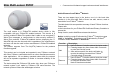
User Instructions

N
O.
Name
Def
.
Valid Description
detected function. And always turn
on the light.
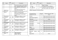
8
LightSensor
Threshold
line 5
5 1 ~ 100
0 means turn off illumination
detected function. And never turn
on the light.
1 means darkest. (500Lux)
99 means brightest.
100 means turn off illumination
detected function. And always turn
on the light.
9
(*)
Operation
Mode
1 All
Operation mode. Using bit to
control.
Caution: The value is unsigned
byte, the range is from 0x00 ~
0xFF.
1
Bit0: Setting the temperature
scale. (1: Fahrenheit, 0:Celsius)
0 Bit1: Reserve.
0 Bit2: Reserve.
0 Bit3: Reserve.
0 Bit4: Reserve.
0 Bit5: Reserve.
0 Bit6: Reserve.
0 Bit7: Reserve.
10
(*) Mult-Sensor
Function
Switch
0 All Multisensor function switch. Using
bit
to control.
Caution: The value is unsigned
N
O.
Name
Def
.
Valid Description
byte,
the range is from 0x00 ~ 0xFF.
0 Bit0: Reserve.
0
Bit1: Disable PIR integrate
Illumination to turn ON the lighting
nodes in the association group 2.
(1:Disable, 0:Enable)
0 Bit2: Reserve.
0 Bit3: Reserve.
0 Bit4: Reserve.
0 Bit5: Reserve.
0 Bit6: Reserve.
0 Bit7: Reserve.
11
(*)
Customer
Function
3 All
Customer function switch, using bit
control.
Caution: The value is unsigned
byte, the range is from 0x00 ~
0xFF.
1 Bit0: Tamper On/Off (1:On, 0:Off)
1 Bit1: Red LED On/Off (1:On, 0:Off)
0 Bit2: Reserve.
0 Bit3: Reserve.
0 Bit4: Reserve.
0 Bit5: Reserve.
0 Bit6: Reserve.
7