
Data Sheet

1/6/2018 1046 User Guide - Phidgets Support
https://www.phidgets.com/docs/1046_User_Guide#Measuring_Resistive_Thermal_Devices_.28RTD.29 6/9
We report the measured voltage in a ratiometric unit known as V/V. This is how the maximum range of sensors that
use strain gauges is usually specified. V/V is the output value in V of the measured sensor, scaled for a 1V sensor
supply voltage. This value will correspond to the physical quantity that the sensor is measuring, regardless of the
actual voltage supplied to the sensor.
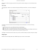
Gain Resolution Range
1 119 nV/V ± 1000 mV/V
8 14.9 nV/V ± 125 mV/V
16 7.45 nV/V ± 62.5 mV/V
32 3.72 nV/V ± 31.25 mV/V
64 1.86 nV/V ± 15.625 mV/V
128 0.93 nV/V ± 7.8125 mV/V
When choosing the Gain setting, it's best to use the highest gain possible that can still measure the full range of
your sensor. For an individual unit, you can apply the maximum stimulus to the sensor, and ensure the voltage ratio
reported is well within the range for the gain setting you have chosen. If many units are being deployed, it’s best to
consult the data sheet for the strain gauge and look for maximum offset.
Some wheatstone bridges, most often those produced from silicon and used in pressure sensors, will have a very
wide offset, and large manufacturing variation in the offset. This will restrict the gain to lower settings, particularly
if the application must support a number of deployed systems with the expected variation. Fortunately, the very
high precision electronics used in the 1046 means that in many application, higher gain is not necessary to get
adequate accuracy and resolution.
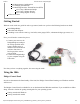
Connecting your Strain Gauge/Load Cell
Load cells are pressure sensors that can be used with the 1046. For more information, see our Load Cell Primer.
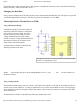
If no documentation is available for your strain gauge, it’s possible to use a multimeter to determine how to
connect it, provided there are no electronics in the sensor. First, measure resistance between the 4 wires. There are
6 combinations - two combinations will have a resistance 20-40% higher than the other four. Choose one of these
high-resistance combinations, and wire it into 5V and G on the 1046. Connect the other two wires into +/-. Apply a
load, if the V/V responds in the opposite way to your expectations, flip the +/- wires.
Measurement Considerations
The 1046 is designed to measure voltages as a ratio of the supply voltage - it’s not practical to make measurements
of absolute voltages with this product.
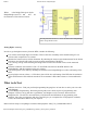
For maximum accuracy, all wires from the 1046 to the sensor should be the same length and thickness. Changes in
temperature will change the resistance of the wires - if they are all the same, the errors will cancel out.