
FlexiForce user manual


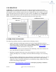

Table Of Contents

02/05/09 FlexiForce Sensor User Manual (Rev G)
12
CALIBRATION
Calibration is the method by which the sensor’s electrical output is related to an actual
engineering unit, such as pounds or Newtons. To calibrate, apply a known force to the sensor,
and equate the sensor resistance output to this force. Repeat this step with a number of known
forces that approximate the load range to be used in testing. Plot Force versus Conductance
(1/R). A linear interpolation can then be done between zero load and the known calibration
loads, to determine the actual force range that matches the sensor output range.
Resistance Curve: Conductance Curve:
CALIBRATION GUIDELINES
The following guidelines should be considered when calibrating a sensor:
• Apply a calibration load that approximates the load to be applied during system use,
using dead weights or a testing device (such as an MTS or Instron). If you intend to use a
"puck" during testing, also use it when calibrating the sensor. See Sensor Loading
Considerations for more information on using a puck.
• Avoid loading the sensor to near saturation when calibrating. If the sensor saturates at a
lower load than desired, adjust the "Sensitivity."
• Distribute the applied load evenly across the sensing area to ensure accurate force
readings. Readings may vary slightly if the load distribution changes over the sensing
area.
• Sensors should be calibrated at the same temperature for which testing will occur. This is
especially important for High-Temp Sensors, as these sensors have a wide operating
temperature range. If multiple temperatures are used during testing, calibrate the sensors
at those same multiple temperatures.
Note: Read the Sensor Performance Characteristics section before performing a Calibration.