
Manual
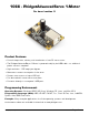
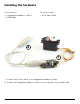
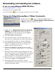
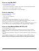

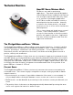


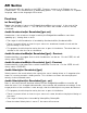
Table Of Contents
- Product Features
- Installing the hardware
- Downloading and Installing the software
- Programming a Phidget
- Technical Section
- The PhidgetAdvancedServo software component uses degrees to specify position, velocity, and acceleration. The degree unit is translated into a pulse sent to the servo, but it’s up to the servo to translate this signal into a particular position. This translation varies between servo models and manufacturers so our degree abstraction will not be exactly the same as the servo you are using. Our degree abstraction is based on the HS322-HD servo, which is typically 10.4uS per degree.
- API Section
- We document API calls specific to the 1066. Functions common to all Phidgets are not covered here. This documentation is deliberately generic. For calling conventions in a specific language, refer to that language’s API manual.
- Device Specifications
- Mechanical Drawing
- Product History

1066_0_Product_Manual created: 07/09/09 Page 3
Testing the PhidgetAdvancedServo 1-Motor Functionality
Double Click on the icon to activate the Phidget Control
Panel and make sure that Phidget Advanced Servo Controller
1-Motor is properly attached to your PC.
Downloading and Installing the software
If you are using Windows 2000/XP/Vista
Go to www.phidgets.com >> Drivers
Download and run Phidget21.MSI
You should see the icon on the right hand corner of the Task Bar.
Double click on1. Phidget Advanced Servo Controller
1-Motor in the Phidget Control Panel to bring up
AdvancedServo-full and check that the box labelled
Attached contains the word True.
The “Choose Servo” box shows 0.2.
Use the Velocity slider to set the velocity limit. The 3.
servo will try to accelerate to this point during motion.
Use the Acceleration slider to set the acceleration.4.
Use the Min/Max Position slider to set the position 5.
range. It can prevent the servo from trying to go
beyond its actual range of motion.
Check the Engaged box to power the servo. If the 6.
servo is not already the target position, it should begin
to move.
Move the Position slider to set a target position. The 7.
servo will turn until its actual position equals the target
position. If Speed Ramping is enabled, the servo will
move using the user set acceleration and velocity.
When the servo has reached the target position, a 8.
tick mark will appear in the Stopped box.
These boxes report the controller’s internally 9.
calculated position and velocity of the servo, as well as
current consumed in amps.
1
2
3
4
5
6
7
9
8