Installation Manual for For Right and Left Hinged Doors Durable. Reliable. Attractive.
Congratulations and thank you for purchasing Viewpoint! The Viewpoint Screen is designed and manufactured by Seiki Screen Systems, the world’s largest manufacturer of retractable screens. Phantom Screens, North America’s leading brand of retractable solutions, is proud to bring you these innovative products. Thanks to rigorous design and product testing, the Viewpoint Screen will provide years of dependable operation.
Index Getting to Know the Viewpoint Screen ................ 4 Parts and Tools ...................................................... 5 Measuring the Door Opening ............................... 6 Cutting the Horizontal and Vertical Parts .................................................. 7 Installing the Bottom Rail and Preparing the Screen Housing Assembly .............. 8 Installing the Mounting Bracket .......................... 9 Installing the Top Rail and Catch Frame ...................
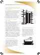
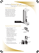
Getting to Know the Viewpoint Before beginning, become familiar with the Viewpoint Screen and the door on which it will be installed. Screen Rollers The Viewpoint Screen accommodates both Top Rail in-swing and out-swing doors. In-swing doors open to the inside of the home and Sliding Bar require the Viewpoint Screen to be installed on the outside of the home. Out-swing doors open to the outside of the Latch home and require the Viewpoint Screen to be installed on the inside of the home.
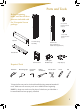
me over Parts and Tools Before beginning, make sure that all these parts are included with the Viewpoint Screen package. 5/8” (16 mm) Pan Head Screws (12 pcs.) g Bracket 1/2” (12 mm) Flat Head Screws (2 pcs.) ip Wire Top Rail Screen Housing Assembly Rail Catch Frame (not required for a double door application) Bottom Rail Required Tools Hack saw Measuring tape Corner Cover Carpenter square Philips screwdriver Sliding Bar Bottom Cap Clips (5 pcs.
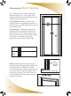
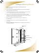
Measuring the Door Opening The Viewpoint Screen requires a minimum Mounting Surface of 1 3/4" (45 mm). This mounting surface must be flat and flush, and at a right angle (90º) to the door. For the Width - Measure the width of the opening between the right and left surfaces of the door frame, record this dimension in the box below labeled “W”.
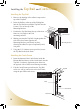
Cutting the Horizontal and Vertical Parts Cutting the Horizontal Parts Calculate the correct cut off Lengths. Maximum Opening Width 36” (914 mm) Subtract inside door frame width “W” Enter Cut off Length Below - = Cut from each part the cut off length provided by the calculation performed above. Top Rail Bottom Rail After cutting any part of the Viewpoint Screen, use a file to remove any burrs from the surfaces.
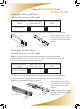
Installing the Bottom Rail and Preparing the Screen Housing Assembly Installing the Bottom Rail Remove the backing from the double sided tape on the bottom of the Bottom Rail. Attach the Bottom Rail onto the door sill, placing the front edge of the Bottom Rail even with the face or front edge of the door frame on both sides of the opening. Bottom Rail Preparing the Screen Housing Assembly 1.
Installing the Mounting Bracket 1. Remove the backing of the adhesive strip on the back of the Mounting Bracket. 2. Insert the bottom of the Mounting Bracket into the track of the Bottom Rail on the hinge side of the door. 3. Push the Mounting Bracket upwards, ensuring that the top of the Corner Cover is tight against the upper portion of the door frame. 4. Using a level, ensure that the Mounting Bracket is positioned plumb.
Installing the Top Rail and Catch Frame Installing the Top Rail 1. Remove the backing of the adhesive tape on the top of the Top Rail. 2. Insert the Rollers at the top of the Sliding Bar into the Top Rail, then push the Top Rail into the Corner Cover on the top of the Mounting Bracket. 3. Position the Top Rail along the top of the door frame at a 90º angle to the side mounting surfaces. Push Corn into the er Co ver Insert Rollers as shown Corner Cover 4.
me Adjusting the Latch and Tension Wires Adjusting the Latch Pull the Sliding Bar over to the Catch Frame and ensure that the Latch can be engaged. If the Latch cannot be engaged, adjust it by following the procedure shown in the diagram. Loosen the screw, adjust the height of the Latch until it engages with the Sliding Bar. Tighten the screw, careful not to over tighten. Loosen the screw to move up and down. Adjusting the Tension Wires 1. Slide the Sliding Bar to the opposite end to engage the Latch.
Attaching the Fixing Strip and Installing the Clips Attach the Fixing Strip Insert one edge of the Fixing Strip into the Mounting Bracket on an angle, beginning at the top, and working toward the bottom. Again from the top, press the other edge of the Fixing Strip into the Mounting Bracket, working it into position all the way to the bottom so that it is now fully inserted into the Mounting Bracket.
racket Service and Maintenance Hints The Viewpoint Screen is designed and engineered to be maintenance free. The following are some helpful hints to ensure the smooth operation of the Viewpoint Screen for years to come. • All moving components used in the Viewpoint Screen are manufactured from a mixture of nylon and other materials. This combination of compounds is strong, impact resistant, and self-lubricating.
Help Hotline The Viewpoint Screen was designed for easy sizing and installation. This Installation Manual provides a step by step guide through the entire process.
Viewpoint Screen Limited Lifetime/Non-transferable Manufacturer’s Warranty The Viewpoint Screen is warranted by Seiki Screen Systems to be free of manufacturer’s defects in materials or workmanship, for as long as the original purchaser owns and or resides at that residence and that the product remains at its original point of installation.
Designed & Manufactured by Seiki Screen Systems ™ Marketed and Distributed by Phantom Screens ® Seiki Screen Systems Call 1-877-446-7180 Or email: info@seikiscreensystems.com Phantom Mfg. (Int’l) Ltd. Call 1-888-PHANTOM Or email: phantom@phantomscreens.com www.seikiscreensystems.com www.phantomscreens.com © 2008 Phantom Mfg. (Int’l) Ltd.