Installation Manual for For Left Hinged Doors Durable. Reliable. Attractive.
Congratulations and thank you for purchasing Sure View! The Sure View retractable screen is designed and manufactured by Seiki Screen Systems, the world’s largest manufacturer of retractable screens. Phantom Screens, North America’s leading brand of retractable solutions, is proud to bring you these innovative products. Thanks to rigorous design and product testing, the Sure View Screen will provide years of dependable operation.
Index Getting to Know the Sure View Screen ........................... 4 Parts and Tools ................................................................ 5 Measuring the Door Opening .......................................... 6 Sizing the Sure View Screen ........................................... 7 Cutting the Top/Bottom Rail and Catch Frame ............... 8 Cutting the Screen Housing Assembly ............................ 9 Installing the Screen Housing Assembly ................
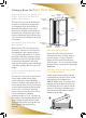
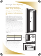
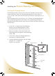
Getting to Know the Sure View Screen Before beginning, become familiar with the Sure View Screen and the door on which it will be installed. Top Rail Sliding Bar Top Rail End Cap Mesh Lock Adjuster The Sure View Screen can be installed on both in-swing and out-swing doors. In-swing doors open to the inside of the home and require the Sure View Screen to be installed on the outside of the home.
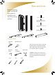
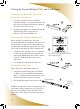
Parts and Tools Before beginning, make sure that all these parts are included in the Sure View Screen package. Stickers, 2pcs. for Latch 5/8” (16 mm) Pan Head Screws, 10pcs. for Mounting Bracket and Catch Frame 1-1/4” (32 mm) Wood Screws, 3pcs. for Top Rail Screen Housing Assembly Bottom Rail Type “A” (used on flat door sills) Mounting Bracket Catch Frame Bottom Rail Type “B” (used on angled door sills) 5/8” (16 mm) Self Tapping Screws, 2pcs.
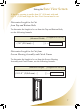
Measuring the Door Opening Now it's time to measure the door opening. The Sure View Screen will accommodate a door opening of up to 36” (914 mm) wide and 81 1/4” (2,064 mm) high. If the door opening is smaller than this, the Sure View Screen will have to be cut. W H For the width, measure the dimension between the right and left sides of the door frame at both the top and bottom of the doorway as indicated in the diagram. Record the smallest of the two sizes in the box labeled “Width” below.
Sizing the Sure View Screen If the door opening is smaller than 36” (914 mm) wide and 81 1/4” (2,064 mm) high, the Sure View Screen must be cut.
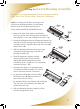
Cutting the Top and Bottom Rail and Catch Frame Cutting the Top Rail of the Sure View Screen is an easy process. 1. Using the “Length to be cut” dimension calculated on Page 7, carefully measure the Top Rail on the end opposite the end cap. Mark on all sides to ensure an even cut. A 2. Wearing safety glasses, cut straight through the Top Rail using either a chop saw or a hacksaw with a bi-metal blade.
gth e cut Cutting the Screen Housing Assembly It is easy to cut right through the Screen Housing Assembly of the Sure View Screen using a chop saw or hacksaw. NOTE: All cutting will be done on the upper end of the Screen Housing Assembly. The Mounting Bracket on the Screen Housing Assembly is clearly labeled with CUT and NO CUT zones. A 1. Remove the Mesh Lock Adjuster and Sliding Bar Top Cap from the Screen Housing Assembly by removing their screws with a Phillips screwdriver. (A) 2.
Installing the Screen Housing Assembly Securing the Mounting Bracket The Mounting Bracket of the Sure View Screen is installed on the left inside surface of the door frame. The ideal minimum dimension of this surface is 1 5/8” (42 mm). This surface must be perfectly flat and at a right angle (90º) to the door. If the mounting surface is greater than 1 5/8” (42 mm), the Mounting Bracket can be positioned anywhere on this surface.
Installing the Screen Housing Assembly Attaching the Screen Housing Assembly 1. Place the front left corner of the Screen Housing Assembly in the outside edge of the Mounting Bracket. (C) 2. Pivot the Screen Housing along this point until the back of the Assembly snaps into the “L” shaped edge on the back of the Mounting Bracket.
Installing the Top Rail 1. Remove the backing on the adhesive strip on the Top Rail. 2. Place the uncapped end of the Top Rail over the Sliding Bar Top Cap and slide the Top Rail into the Mesh Lock Adjuster. Ensure that it fits tightly. (A) 3. Align the Top Rail so that the edge of the Top Rail End Cap closest to the door is in a straight line to the “L” shaped edge of the Mounting Bracket.
Installing the Catch Frame 1. Insert the Catch Frame into the bottom of the Top Rail End Cap. Ensure that the Top Rail End Cap fits tight to the right side of the door frame. (D) 2. Using a level, adjust the Catch Frame along the mounting surface of the door frame to ensure that it is positioned plumb. It is important that the bottom of the Catch Frame fits tight to the door sill. (E) 3. Attach the Catch Frame to the door frame using the 5/8” (16 mm) Pan Head Screws provided.
Installing the Bottom Rail If the Bottom Rail did not require cutting, it is important to select the correct Bottom Rail for installation. The Sure View Screen package comes with two Bottom Rails to accommodate both flat and angled door sill. Please refer to (A) to determine the correct Bottom Rail. 1. Remove the backing on the adhesive strip on the Bottom Rail. Bottom Rail Type“A” A 2.
Adjusting the Catch 1. Loosen the screw on the Catch. 2. Move the Catch up and down to determine the position where the Latch makes a secure contact with the Catch. Tighten the screw on the Catch to secure it in place. (D) 3. Adhere the Stickers to the front and rear of the Latch as indicated.
Final Adjustments Adjusting the Mesh Mesh Lock Adjuster Dial Lock A Spring Tension Adjuster Dial B Increase Spring Tension The Sure View Screen can be adjusted to reduce the amount of mesh discharged from the Screen Housing. This keeps the mesh tight to maintain the effectiveness of the Sure View Screen in keeping out unwanted insects. 1. Close the Sure View Screen. 2. Turn the dial on the Mesh Lock Adjuster as indicated in illustration (A) until meeting with resistance, but without over-tightening.
Service and Maintenance Hints The Sure View Screen is designed and engineered to be maintenance free. Please review these helpful hints to ensure the smooth operation of the Sure View Screen for years to come: • All moving components used in the Sure View Screen are manufactured from a mixture of nylon and other materials. This combination of compounds is strong, impact resistant, and self-lubricating.
Help Hotline The Sure View Screen was designed for easy sizing and installation. This Installation Manual provides a step by step guide through the entire process.
Sure View Screen Limited Lifetime/Non-transferable Manufacturer’s Warranty The Sure View Screen is warranted by Seiki Screen Systems to be free of manufacturer’s defects in materials or workmanship, for as long as the original purchaser owns and or resides at that residence and that the product remains at its original point of installation.
Designed & Manufactured by Seiki Screen Systems ™ Marketed and Distributed by Phantom Screens ® Seiki Screen Systems Call 1-877-446-7180 Or email: info@seikiscreensystems.com Phantom Mfg. (Int’l) Ltd. Call 1-888-PHANTOM Or email: phantom@phantomscreens.com www.seikiscreensystems.com www.phantomscreens.com © 2008 Phantom Mfg. (Int’l) Ltd.