WORKSHOP MANUAL 50 cm3 Motor FB-0-1-2-4 GB
CONTENTS CYCLE PART ENGINE PART Designation Page - Contents, ............................................................. - Main characteristics, ............................................ - Maintenance plan, ................................................ - Putting into service, ............................................. - Special tools,........................................................ - Tightening torques ...............................................
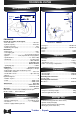
TECHNICAL DATAS Main spécifications Frame ENGINE MARKING IDENTIFICATION MARK Number Type XXXXXXXX FB2 Identification plate FB2 ENGINE Forced-air cooled 2 stroke engine : - Bore and stroke : ................................................ 40 x 39.1 - Cylinder capacity : ............................................. 49.13cm3 - Compression ratio : ................................................... 6.6:1 - Maximum power (ISO) : .......................................... 3.
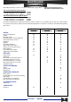
MAINTENANCE MAINTENANCE PLAN Depending on how the scooter is used, it is recommended to apply either - The normal maintenance plan or - The reinforced maintenance plan.
INSTRUCTIONS FOR MAKING OPERATIONAL 1. Preparation of the battery (dry charged) - Remove the battery. - Remove the six cell caps and the breather tube cap. - Fill the battery with électrolyte up to the level marked UPPER LEVEL (35% sulphuric acid 1.28 g/CM3), Ref : ........................................................... 1 litre : 752740 ................................................................ 5 litres : 752741 - Leave the battery to settle for half an hour. Top up the level if necessary.
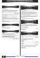
TIGHTENING TORQUES AND SPECIAL TOOLS TIGHTENING TORQUES SPECIAL TOOLS Assembly screws for : - Housings : ........................................................ 1m.daN - Covers : ............................................................ 1m.daN - Intake connecting part : .................................... 1m.daN - Starter motor : .................................................. 1m.daN - Stator : .............................................................. 1m.daN - Sensor : ......................
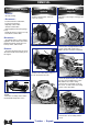
REMOVAL Removal of the engine Removal of cooling systern Removal of the flywheel magneto - Remove : - All side casings - Remove the two parts of the fan covers (4 screws). - Disconnect : - Block the rotor using a notch type pin 752237.
REMOVAL Removal of the oil pump Removal of the primary drive system You do not have to remove of the kick starter arm when removing the crankcase cover. - Loosen and remove the 11 fastening screws of the cover. - Unclip the oil inlet pipe to the carburettor. - Unscrew the 2 hex head socket screws. - Remove the oil pump and the control flange. - Remove the 2 square fastening nuts Q from their housings. - Remove the flexible washer lodged between the pump and the shaft bearing of the oil pump.
REMOVAL Make careful note of where this tool comes level with the starter ring gear plate of the starter motor in order to make sure, when refitting, that the pressure plate fits correcte into the grooves of the crankshaft. - Loosen the fastening nut (right-hand thread) of the gear plate of the drive pulley. - Remove the nut, washer and plate. - Remove the belt. - Remove the drive pulley assembly (variable speed drive) and the washer on the engine housing side (12,35 X 19,75 X 1).
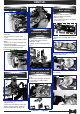
REMOVAL Removing the cylinder and piston - Remove the cylinder and cylinder-tocrankcase gasket. - Pack the crankcase mouth with clean cloth or paper. - Turn the inner thrust bolt of tool 750807 until the crankcase halves split Hold the connecting rod so that it does not knock against the crankcase halves. - Remove the RH half casing. - Remove the gasket and both locating dowls. Remove the drive shaft of the oil pump and its locating bush. - Secure the plate to the crankcage by tightening the 4 screws.
REFITTING Refitting the engine Assembly of the crankshaft into the left hand crankcase: - Fit the crankshaft into the bearing. - Screw the ex tended nut 750069 onto the end of the crankshaft. 64706 Closing the crankcase halves - Position both locating dowls in the LH crankcase: - Put the crankcase gasket in place (no oil, no grease). Refitting the piston - Check the cylinder and piston parts are a matched pair.
REFITTING Refitting the cylinder - The parting face should be cleaned. - Lubricate the piston and the cylinder bore. - Fit a new and dry cylinder base gasket onto the cylinder. - Make sure that the piston ring end gaps are aligned with the positioning slots. - Position the cylinder and push it down while squeezing the piston rings bet-ween your thumb and middle finger. - Make sure the cylinder base gasket is correctly positioned on the crankcase using 2 threaded bolts.
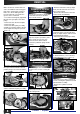
REFITTING / FITTING Instailing the kick starter (LH cover) - Fit the spindle bushing and the nylon spacer (mark 1). 1 - Position the return spring, fit the longest hook onto the pin on the cover. - Instail the spindle into the bushing after lubrication. - Fit the second hook of the spring onto the toothed section. - Wind the spring slightly so as to position the kick starter spindle onto the central rib of the cover. - Install the washer and circlips onto the axis of the toothed section.
FITTI NG Fitting of the «clutch drive pulley» assembly and the belt Fitting the reed valve and intake pipe - Introduce the belt to the bottom of the groove of the driven puiley by pulling apart the drive faces using both hands. - Position the belt on the drive pulley. - Fit the «clutch / drive pulley» assembly onto the primary shaft of the transmission. - Position the clutch casing and tighten the nut to 4.5m.
FITTING Fitting of the oil pump - Position both square nuts (Q) in their housings. - Place the flexible washer on the seat. - Position the pump fitted with its «0»ring, position the sheath stop fastening hook and fasten the cluster with two n».4 hex head socket screws. - tighten to 0.8m.daN. Adjustment of the oil purnp 1) Check the free play in the throttle grip (2 to 5mm) and adjust if necessary using the adjusting screw. 2) Open the throttle fully.
ELECTRIC EQUIPMENT 3 IGNITION 1 a Operating principle : The ignition coil charges a condenser in the CDI unit. Passage of the rotor pad in front of the sensor authorises the discharging of the condenser in the primary winding of the high voltage coil via a thyristor, in order to generate through transformation in the secondary, a voltage in the region of 20 000 volts at the spark plug.
ELECTRIC EQUIPMENT Note : The rear bulb is composed of 2 filaments, one 5W filament supplied with alternating current for the taillight, one 21 W filament supplied with direct current for the stop light. 1/ Solving lighting faults - Check the bulbs; power, voltage, compliance with European standards (El). - Check the connections (especially those of the regulator). - Check the voltage using a multimeter (MX40) set to the AC voltmeter position.
ELECTRIC EQUIPMENT 1 - Flywheel c : alternative current d : battery charge current 2 - Ignition switch 7 - Regulator, rectifier b : regulator, rectifier (DC) 14 - Rear and stop light 15 - Battery 16 - 5A Fuse 17 - Horn 18 - Horn button 19 - Indicator control 21 - Indicator bulbs D - Indicator telltale 22 - Fuel gauge E - Fuel gauge receiver 23 - Stop contact switch 24 - Starter motor relay 25 - Starter motor control 26 - Starter motor 27 - Current limiter 28 - Low oil level contact switch C - Low oil level
ELECTRIC EQUIPMENT 1. Key switch to OFF No display should appear on the multimeter. If a value is displayed (for example 0.5mA), either the regulator (connection wires) or the key switch is faulty. 2. Key switch to ON A slight discharge can be explained by sending a volt supply to the fuel gauge and to the oil low level warning light (0.9mA to 1OOmA maximum). A significant dischar@e indicates a more or less earthed circuit.
ELECTRIC EQUIPMENT STARTER MOTOR CIRCUITS Operating principle : The starter motor requires two circuits. 1. Control circuît : 27 0,75Ω 4w 14 5/21w 5A 3 1 2 12V 4Ah 5 off 4 15 16 on This consists of the following elements connected in series: Battery, fuse, key switch, stop switches, starter motor relay, start switch (START).
20 c Trekker - Squab 6 5kΩ 5 5kΩ 1 d 10 8 4 a b b a 3 7 17 18 4 1 on 6 C 28 5 2 1,2w off 3 9 21 1,2w D 4x 10w 11 5,9Ω 30w 6,7Ω 5w 20 19 E 16 5A 14 23 10Ω 100Ω 22 5/21w 25 24 B 1,2w A 3 x 1,2w 26 12V 4Ah 15 27 0,75Ω 4w 15w 13 Squab 50 without dipped headlights
4 a b b a 3 7 Trekker - Squab 17 18 4 1 on 6 5 2 28 1,2w C off 3 11 5,9Ω 30w 6,7Ω 5w 9 21 D 1,2w 20 19 13 12 L 35/35w E H 23 16 22 5A 10Ω 5/21w 24 25 27 5w 26 12V 4Ah 15 0,75Ω 4w 3 x 1,2w 1,2w 14 A B 33 Trekker 50 all types and Squab 50 with main beam + dipped headlights 21
KEY TO ELECTRIC CIRCUITS A B C D E Instrument panel lighting Headlamp telltale Low oil level telltale Indicator telltale Fuel gauge receiver 1 Flywheel a ignition b sensor c alternative current d battery charge current 2 3 4 5 6 7 Ignition switch CDI ignition unit High voltage coil Interference suppresser 5 KW Spark plug 5 KW Regulator, rectifier a regulator (AC) b regulator, rectifier (DC) 8 9 10 11 12 13 14 15 16 17 18 19 20 21 22 23 24 25 26 27 28 33 Choke Resistance 6,7 W - 5 W Lighting control
Note 2 Trekker - Squab 23
INTRODUCTION This workshop manual concerns the FB engine which is fitted on several 50cm3 vehicles on the air-cooled version: - FB0 ............................................ ZENITH - FB1 ............................................ BUXY - SPEEDAKE - FB2 ............................................ SQUAB - TREKKER - FB4 ............................................ SPEEDFIGHT - TREKKER ROAD The electric part of this manual only concerns the TREKKER and SQUAB vehicle ranges.
N° 11.753784.00 Dans un souci constant d'amélioration Peugeot Motocycles se réserve le droit de modifier, supprimer ou ajouter toute référence citée DC/PS/SH Imp. en U.