
Data Sheet


User Manual
WiLoader Revision G
Hardware tips
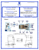
Normally, the supply voltage and VCCIO are connected by the R1 resistor. As a result, if the
power supply voltage applied to the WiLoader is different from IO voltage of the MCU (for
example, 3.3v as supply voltage and 1.8v for IO voltage), the user must disassemble the R1
resistor and supply VCCIO through the VIO pin which is on the right corner of WiLoader.!
Note: In case of different VCCIO and power supply voltage, the VCCIO circuit in the WiLoader
doesn't have over-voltage, reverse-voltage or over-current protections.!
The MOSI, MISO, RXD, RESET pins inside WiLoader are connected to the level translator or
buffer IC’s input, so if they are not connected to the user's circuit (for example, the user only
uses the WiLoader in boot loader or serial mode And does not use MISO and MOSI pins)
These pins will be float and may add up to a few mA to total current consumption.
Consequently, if the current consumption is of high importance, a 33 KOhms resistor can be
used instead of each of the resistors R18 (MISO), R19 (RXD), R20 (Reset) and R31 (MOSI).!
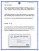
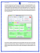
How to set up
For connecting WiLoader to the preferred WiFi network, first attach the appropriate voltage to
the power supply terminals. As a result, if WiLoader turns on the power LED (White LED) will
light up. Next, press and hold the S button for at least 1 second. After releasing the button,
WiLoader will go to Access Point mode and creates a Wi-Fi network, which is the same name
as WiLoader itself. WiLoader’s name should be WiNew_A, WiNew_B, WiNew_C or WiNew_D
after production. (Note: This name can be changed at any given time by user)!
3