yardmax ™ rechargeable in-ground fence ™ operating and training guide Model Number PIG00-11115 Please read this entire guide before beginning
Customer Care Center 1-800-732-2677
Thank you for choosing PetSafe®, the best selling brand of electronic training solutions in the world. Our mission is to be the most trusted brand in the pet ownership experience. We want to ensure your pet’s safety by providing you with the tools and techniques to successfully train your pet. If you have any questions, please contact the Customer Care Center at 1-800-732-2677 or visit our website at www.petsafe.net.
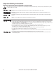
Important Safety Information Explanation of Attention Words and Symbols used in this guide This is the safety alert symbol. It is used to alert you to potential personal injury hazards. Obey all safety messages that follow this symbol to avoid possible injury or death. WARNING indicates a hazardous situation which, if not avoided, could result in death or serious injury.
This PetSafe® In-Ground Fence™ is not a solid barrier. This system is designed to act as a deterrent to remind dogs by Static Correction to remain in the boundary established. It is important that you reinforce training with your dog on a regular basis. Proper fit of the collar is important. A collar worn for too long or made too tight on the dog’s neck may cause skin damage. Ranging from redness to pressure ulcers; this condition is commonly known as bed sores.
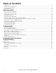
Table of Contents Components...................................................................................................................................................... 7 Other Items You May Need.............................................................................................................................. 7 How the System Works..................................................................................................................................... 8 Key Definitions......
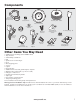
Components 5 6 4 3 Receiver Collar w/Short Contact Points 7 A 8 B 2 9 1 10 Long Contact Points Boundary Wire - 500 ft. Fence Transmitter After opera verifying labels tion at the Receiver Colla to ident boun connectio ify the dary, user the Boun ns to Boundary the the Trans dary Wire to the Wire conve Surge Prote conn mitter and wires nient to have ctor. Thisections become will disco should any be nnected.
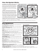
How the System Works The YardMax™ Fence Transmitter sends a radio signal through a buried wire, marking the boundaries you wish to set for your dog. Your dog wears a Receiver Collar that detects the signal at the boundary. The Receiver Collar offers 5 levels of correction plus toneonly, adjustable to your dog’s temperament. The Fence Transmitter operates in two modes: YardMax™ or Traditional.
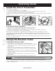
Operating Guide Step 1 Install the Fence Transmitter Place the Fence Transmitter: In a dry, well ventilated, protected area (1A, 1B). In an area where temperatures do not fall below freezing (e.g., garage, basement, shed, closet). Secured to a stationary surface using supplied mounting hardware. At least 3 feet from large metal objects or appliances as these items may interfere with the signal consistency (1C). • In an area that can be accessed easily so that you can hear and respond to alarms.
Step 3 Prepare the Receiver Collar Your Receiver Collar comes with short Contact Points installed. Use the long Contact Points for dogs with long or thick hair. Tighten the Contact Points using the Contact Point Wrench (3A). Check the tightness weekly. The Receiver Collar is waterproof. 3A To Turn On the Receiver Collar Press and hold the Mode Button for 1 second (3B).
If the Receiver Collar fails the ReadyTest®, the collar is automatically turned OFF. Your pet will not be contained. When the collar is removed from the charger, or turned on, the indicator light will go off for 1 second. The indicator light will come back on for five seconds to indicate the status of the battery (green, yellow or red). The ReadyTest® is complete once you see the battery indicator status. You may place the Receiver Collar on your pet after the ReadyTest® is complete.
Over Correction Protection YardMax™ mode: In the unlikely event that your pet “freezes” or continues beyond the boundary, the Static Correction duration continues for 15 seconds. The Receiver Collar locks out further Static Correction and the green light will remain on for 10 seconds. The Receiver Collar remains locked out until the pet re-enters the Pet Area.
Traditional Mode Layouts Both previous sample layouts may be also be used in Traditional Mode (4C, 4D). Sample 3 (4E): Perimeter Loop with Exclusion Areas (Single Loop) This layout allows you to keep your dog out of gardens, pools or landscaping within your yard. A Double Loop layout must be used when you are not establishing the Boundary Zone on all sides of your property. When using a Double Loop, the Boundary Wire must be separated by a minimum of approximately 5 FEET to avoid canceling the signal.
4F 5’ Containment Area A D 5’ E G 5’ B G B D Place Transmitter inside G A E A C F 5’ F G A Place Transmitter inside C Sample 4 (4F): Front or Back Yard Only (Double Loop) From the Fence Transmitter, run the wire to A, A to B, B to C, C to D, D to E, E to F, make a U-turn and follow your path all the way back to G, keeping the wire separated by at least 5 feet. When you get back to the house (G), make a sharp turn along the side of the house back to A.
Lay out the Boundary Wire using your planned boundary and test the system BEFORE burying the wire or attaching it to an existing fence. This will make any layout changes easier. Work carefully. A nick in the wire insulation can diminish the signal strength and create a weak area where your dog can escape. Ensure you have at least 10 feet between the wire and dangerous areas such as the street.
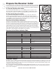
Additional Boundary Wire Extra direct burial Boundary Wire can be purchased in 500 foot spools at the store where you purchased the kit or through the Customer Care Center. Note: When adding wire, it must act as a continuous loop. The table at right indicates the approximate length of Boundary Wire needed for a square, Single Loop layout. Length will vary due to the amount of twisted wire and layout used.
13. Turn the Fence Transmitter ON. The Indicator Light on the Transmitter should illuminate to green indicating a properly installed boundary loop. If the alarm sounds and Warning Light illuminates red, check the connections to make sure there isn’t an open circuit. If still not operating correctly, refer to the “Troubleshooting” section in this guide.
Step 8 A Step 8 B 18 Test Receiver Collar in YardMax Mode ® • In YardMax™ mode, excessive snowfall (>1.5 ft) may place your dog outside the signal field allowing your dog to leave the Pet Area. You may need to switch to Traditional Mode or increase the boundary width until the snow recedes. Follow the steps below to set the appropriate level in YardMax® mode. By setting the appropriate level, you will improve Receiver Collar battery life.
8. Adjust the Boundary Width Dial so that the Receiver 8A 8B Collar tones within the desired range of the Boundary Wire. To best use the automatic RunThrough Prevention feature, the Boundary Width should extend at least 10 feet from the Boundary Boundary Wire (total Boundary Width of 20 feet). Wire Boundary 9. Test in a number of different locations around the Wire pet area until you are satisfied that the system is functioning properly. 10.
Step 9 Install the Boundary Wire S • Underground cables can carry high voltage. Have all underground cables marked before you dig to bury your wire. In most areas, this is a free service. Avoid these cables when you dig. • Before you begin installing the Boundary Wire, turn the Fence Transmitter OFF and unplug the adapter from the Surge Protector. To Bury the Boundary Wire 10 Burying the Boundary Wire is recommended to protect it and prevent disabling the system. 1.
Step 10 Step 11 Place the Boundary Flags The Boundary Flags are visual reminders for your pet of where the Warning Zone is located. YardMax™ mode: 1. Place the Boundary Flag along the Boundary Wire approximately 6 inches inside the Pet Area (10A, 10B). 2. Place a Boundary Flag in the ground every 10 feet. Boundary Wire 10A 10B Traditional Mode: 1. Place the Test Light Contacts on the Contact Points. Hold the Receiver Collar at your pet’s neck height. 2.
4. Check the tightness of the Receiver Collar by inserting one finger between the end of a Contact Point and you pet’s neck. The fit should be snug but not constricting. 5. Allow your dog to wear the collar for several minutes, then recheck the fit. Check the fit again as your dog becomes more comfortable with the Receiver Collar. 6. Once you are satisfied with the fit of the Receiver Collar then you may trim any excess collar strap as follows (11C). a.
Training Guide Be Patient With Your Pet Important: Proper training of your pet is essential to the success of the Petsafe® YardMax™ Rechargeable In-Ground Fence™. Read this section completely before beginning to train your pet. Remember that this PetSafe® YardMax™ Rechargeable In-Ground Fence™ is not a solid barrier. • Have fun with your pet throughout the training process. Training should be fun, fair, firm and consistent. • Train for 10 to 15 minutes at a time. Don’t try to do too much too quickly.
Steps: 1. Begin by walking your pet on a leash in the Pet Area. Calmly praise and talk to your pet. 2. Move toward the Boundary Flags (12A). Keep your mood happy. 3. With full control of your pet on a leash, walk to the flags. As your pet enters the Static Correction Zone, the Receiver Collar will begin to beep (12B). Allow him to stay in the Static Correction Zone for up to 2 seconds then gently help him back into the Pet Area (12C).
Setup: • Set the Static Correction Level Receiver Collar to level 2 or higher, depending reactions results from days 2 thru 4. Place the Receiver Collar on your pet. • Put a separate non-metallic collar on your pet’s neck ABOVE the Receiver Collar and attach a leash. Be sure the extra collar does not put pressure on the Contact Points. • Have tiny pieces of treats available (hot dogs or lunch meat work well). • Have your pet’s favorite play toy available.
Phase 5 Days 15 thru 30 - Pet Monitoring Your pet is ready to run! Check in on your pet at regular intervals. Note: After you are satisfied your pet’s training is complete, remove every other Boundary Flag every 4 days until all flags are removed. Save Boundary Flags for future use. Taking Your Pet Out of the Pet Area Important: Remove the Receiver Collar and leave it in the Pet Area. Once your pet learns the Boundary Zone, he will be reluctant to cross it for walks or car rides.
Accessories To purchase additional accessories for your PetSafe® YardMax™ Rechargeable In-Ground Fence™, contact the Customer Care Center or visit our website at www.petsafe.net to locate a retailer near you.
Frequently Asked Questions Is the Receiver Collar waterproof? What happens if the power goes out? If my pet leaves the Pet Area, how long will he be corrected? How often do I need to charge the Receiver Collar battery? Can I place the Receiver on another collar? What do I do if my pet’s neck becomes red and irritated? Can I attach a leash to the Receiver Collar? Why does my Receiver Collar have a tone only mode? • Yes. • Your pet will no longer be contained. Be sure to contain by another means.
I have an inconsistent signal. Transmitter status light and alarm indicates Boundary Wire is broken or disconnected. No status light on the Fence Transmitter and alarm is silent. Receiver Collar is not charging. In YardMax Mode, my dog is able to cross the Boundary Wire in either direction without receiving a Static Correction. In YardMax mode, the Receiver Collar corrects within the Pet Area. My pet reacts strongly to the Static Correction and has become fearful.
System Test The system test is used to determine the cause of system problems that have not been addressed elsewhere in this guide. You will need a piece of Boundary Wire greater than 15 feet long with 3⁄8 inch of insulation removed from each end to use as a test loop wire. Make a note of your Boundary Width Dial setting, and Receiver Collar setting before beginning the System Test. Follow the steps below to perform the system test: 1.
Wire Break Location Test The following lists identify the common locations where wire breaks occur. Please inspect these areas for signs of damage. Wire breaks in the twisted pair are commonly found: 1. At the wire exit point of the house 2. Where the twisted pair of wire enters the ground from the house, usually caused by string trimmers 3. Where the wires cross sidewalks or driveways due to edging and string trimmers 4.
Terms of Use and Limitation of Liability 1. Terms of Use This Product is offered to you conditioned upon your acceptance without modification of the terms, conditions and notices contained herein. Usage of this Product implies acceptance of all such terms, conditions, and notices. 2. Proper Use This Product is designed for use with pets where training is desired. The specific temperament of your pet may not work with this Product.
Customer Care International Canada - Tel: 800-732-2677 Monday - Friday 8 AM - 8 PM / Saturday 9 AM – 5 PM Australia - Tel: 1800 786 608 Monday - Friday 8:30 AM - 5 PM New Zealand - Tel: 0800 543 054 Monday - Friday 10:30 AM - 7 PM This product has the benefit of a limited manufacturer’s warranty. Details of the warranty applicable to this product and its terms can be found at www.petsafe.net and/or are available by sending a stamped addressed envelope to PetSafe® Ltd.
Customer Care Center 1-800-732-2677
www.petsafe.
Layout Grid Radio Systems® Corporation 10427 PetSafe Way Knoxville, TN 37932 1-800-732-2677 www.petsafe.net Protected by US Patents 6,184,790; 6,327,999; 6,459,378; 6,807,720; 7,046,152; 7,068,174; 7,117,822; 7,204,204; 7,278,376; 7,345,588; 7,394,390; 7,495,570; 8,047,161; and 8,342,135.