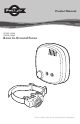
Product Manual PIG00-14582 ZIG00-16969 Basic In-Ground Fence™ ARF 67 TT BA Y6 ER V Please read this entire product manual before beginning
Welcome You and your pet were made for each other. Our aim is to help you have the best companionship and the most memorable moments together. Your Basic In-Ground Fence™ system is designed to give your pet more freedom while keeping him safe. We know that safe pets make happy owners. Before getting started, please have your utilities marked, and take a moment to read through the important safety information. If you have any questions, please don’t hesitate to contact us.
• Wire on top of the ground may be a trip hazard. Be careful when placing wires and testing the system. • This product is not a toy. Keep it away from the reach of children. • This PetSafe® Basic In-Ground Fence™ system is NOT a solid barrier. It is designed to act as a deterrent to remind pets to remain within the established boundary by use of static correction. It is important that you reinforce training with your pet on a regular basis.
• Avoid damaging the insulation of the loop wire; damage may cause areas of weak signal and lead to failure of the boundary. • Use care when mowing or trimming your grass not to cut the loop wire. • Plug the surge protector into a grounded (3-prong) outlet that is within 5 ft. of the fence transmitter. ALWAYS use a grounded (3-prong) outlet to ensure maximum protection. • Do not remove the ground prong from the surge protector plug. Do not use a 3-prong plug to 2-prong outlet converter.
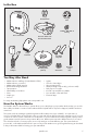
In the Box Long Contact Points Test Light Tool PetSafe® RFA-67D-11 Battery Fence Transmitter Receiver Collar with Short Contact Points Surge Protector Power Adapter Gel-filled Capsules Boundary Wire (500 ft.
Key Definitions Fence Transmitter: Transmits the signal through the boundary wire. Pet Area: The area within the warning zone where your pet can roam freely. Receiver Collar Receiver Indicator Light Battery Warning Zone: The outer edge of the pet area where your pet’s receiver collar begins to beep, warning him not to go into the static correction zone.
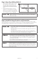
Step 1: Have Your Utilities Marked 1. Call your utility company to have your utility lines marked. If you have neighbors using an in-ground pet containment system, you will want to ask them where the boundary is located. Place your wire at least 10 ft. away from it. 2. Large metal objects and wires can cause interference in unpredictable ways. Make a plan for how you will work around any large metal objects, like sheds or existing wires. You can cross utility lines at a 90° angle (1A).
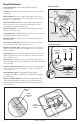
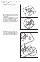
1. Find a place to install the surge protector and transmitter. There are a few things to consider when choosing an outlet for your surge protector and transmitter: • We recommend using an outlet at least 30 ft. from the breaker box. • Both the surge protector and transmitter should be indoors, in a dry, ventilated and protected area (2A, 2B). • The boundary wire must run from the transmitter and exit the building, so place the transmitter near a window or a wall that you can drill through (2A).
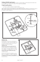
Step 3: Design Your Boundary Zone Basic Planning Tips • Always design your layout, position the boundary wire and test the system as outlined in this product manual before burying the boundary wire. You do not want to find out after burying the wire that there is a problem with your layout or a loose connection somewhere. • Sample layouts are provided in this section. • The boundary wire must start at the fence transmitter and make a continuous loop back (3A).
Single or Double Loop Layout The containment area can be created by using either a single boundary wire that is placed around the entire property (3C) or by doubling the boundary wire along the same path (3E).
Double Loop Boundary • To section off only one boundary area or one section of your yard (e.g., front property only, or waterfront property) • The 2 parallel sections of the double boundary wire must be separated by a minimum of approximately 5 ft.
Step 4: Position, Twist and Splice the Boundary Wire Once you have designed your layout, the next step is to position the wire. Hold off on burying the wire until you have tested the system first. 4A • Start with one end of the wire at the transmitter, but do not turn it on yet. Run the wire all the way around your planned perimeter and back to the transmitter. Off-limits Areas 4B ³⁄₈ in. ³⁄₈ in.
Step 5: Connect the Wires Now that the boundary wire has been positioned and spliced, the next step is to connect the wire that is running from outside to the surge protector, and then to the transmitter. Make sure the boundary wire is not cut off or pinched by a window, door, or garage door, as this can damage it over time. • Do not install, connect or remove your system during a lightning storm. If the storm is close enough for you to hear thunder, it is close enough to create hazardous surges.
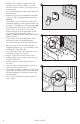
Step 6: Prepare the Receiver Collar There are two sets of contact points that can be used on your receiver collar. Your receiver collar comes with the short contact points installed. The longer contact points should be used on dogs with long hair. Tighten the contact points using test light tool one-half turn beyond finger tight. Check the tightness weekly. Insert and Remove the Battery Note: Do not install the battery while the receiver collar is on your pet.
Function and Response Table Indicator Light Static Correction Level Receiver Collar Function 1 red flash 1 None—tone only 2 red flashes 2 Low correction 3 red flashes 3 Medium correction 4 red flashes 4 Medium-high correction 5 red flashes 5 High correction Flashes once every 4 to 5 seconds – Indicates low battery Anti-Linger Prevention The anti-linger prevention feature keeps your pet from staying in the warning zone for long periods of time and draining the receiver collar battery.
Step 7: Set the Boundary Width and Test the Receiver Collar With the boundary wire in place and properly connected, it is time to set the boundary width and test the system. Always remove your pet’s receiver collar before performing any transmitter testing or adjustments. This will prevent unintended static corrections. Note: The receiver collar is waterproof, which can make the tone hard to hear.
7. Turning the boundary width control knob clockwise increases the boundary width, while turning it counter clockwise decreases it (7E). Repeat this activity as needed until the receiver collar tones between 6 to 10 ft. from the boundary wire. If using a double loop layout, you may need to increase the separation of the boundary wire and/or increase the size of the boundary width to achieve the desired range. 8.
Step 8: Bury the Boundary Wire Underground cables can carry high voltage. Have all underground cables marked before you dig to bury your wire. In most areas, this is a free service. Avoid these cables when you dig. Before you begin installing the boundary wire, unplug the fence transmitter. It is recommended to bury the boundary wire to protect it and prevent disabling the system. 1. Cut a trench 1 to 3 in. deep along your planned boundary. It only needs to be as wide as the wire.
Follow all safety instructions for your power tools. Be sure to always wear your safety goggles. Cross Hard Surfaces (driveways, sidewalks, etc.) 8C 8D • Concrete Driveway or Sidewalk (8C): Place the boundary wire in a convenient expansion joint or create a groove using a circular saw and masonry blade. Place the boundary wire in the groove and cover with an appropriate waterproofing compound. For best results, brush away dirt or other debris before patching.
Step 10: Fit the Receiver Collar • Proper fit of the receiver collar is important. A receiver collar worn for too long or made too tight on the pet’s neck may cause skin damage, ranging from redness to pressure ulcers; this condition is commonly known as bed sores. • Avoid leaving the receiver collar on the pet for more than 12 hours per day. • When possible reposition the receiver collar on the pet’s neck every 1 to 2 hours.
Training • Remember that this system is not a solid barrier. Using it successfully requires that you spend some time training your pet. • Finish each training session on a positive note with lots of praise and play. Remove the collar after each training session. • While your pet is still learning the boundary, contain him by another means, such as with a pen or a leash. • Be sure to place the collar on your dog’s neck with the PetSafe® logo facing up.
Days 9–30 Once your pet consistently respects the boundary regardless of distractions or temptations, he is ready for the next step: unleashed supervision (11D). Stay close by with a leash at hand. Play with your pet for a while during the first few sessions. If your dog does not try to cross the boundary, occupy yourself with another task in the yard, and allow him to freely explore. Continue watching your pet. If he escapes, remove the collar and lead him back into the pet area.
System Test The system test is used to determine the cause of system problems that have not been addressed elsewhere in this product manual. You will need a piece of boundary wire greater than 15 ft. long with 3⁄8 in. of insulation removed from each end to use as a test loop wire. Make a note of your boundary width dial setting, and receiver collar setting before beginning the system test. 12A Follow the steps below to perform the system test: 1.
Wire Break Location Test The following lists identify the common locations where wire breaks occur. Please inspect these areas for signs of damage.
Troubleshooting The receiver collar is not beeping or correcting. • Check the battery to make sure it is installed properly. • Check that both lights are lit on the fence transmitter. If not, perform the “System Test.” The receiver collar is beeping, but the pet is not responding to the static correction. • Test the receiver collar with the test light by walking toward the boundary wire. If the test light flashes, adjust the fit of the receiver collar.
The power and loop indicator lights are off. • Check that the power adapter is plugged into the fence transmitter. • Check that the power adapter is plugged in properly. • If the system is plugged into a RCD or GFCI outlet, check to see if the circuit has been tripped. Reset the RCD or GFCI circuit if required. • Verify that the outlet is working properly by plugging in a known working item such as a radio. • Try plugging the fence transmitter into another 120-volt outlet.
Compliance FCC This device complies with part 15 of the FCC Rules. Operation is subject to the following two conditions: (1) This device may not cause harmful interference, and (2) this device must accept any interference received, including interference that may cause undesired operation. Note: This equipment has been tested and found to comply with the limits for a Class B digital device, pursuant to part 15 of the FCC Rules.
Mounting Template Drill here 3 in. Drill here Radio Systems Corporation 10427 PetSafe Way Knoxville, TN 37932 USA +1 (800) 732-2677 petsafe.com For a list of patents protecting this product, please visit www.radiosystemscorporation.