
Owner's Manual
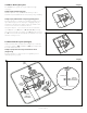
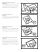
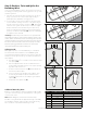
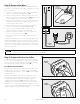
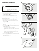
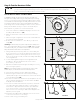
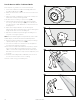
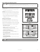
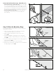
Table Of Contents

1- 8 0 0 - 732 - 26 7 716
Step 8: Test the Fence Direction
You will want to verify that your fence is transmitting in the right direction
to contain your pet. You will need to do this test in YardMax
®
mode,
regardless of which mode you plan to use.
• The receiver collar should NOT be on your
pet when the system is tested. Your pet may
receive an unintended correction.
• To prevent an unintended correction for your
pet, test the boundary location and width
after any change.
1. Make sure the fence transmitter is on and that the receiver collar
has been charged.
2. Set the fence transmitter to YardMax mode (A) and turn the
boundary width dial to 3 (8A).
3. Turn on the receiver collar by holding the mode button for
1 second.
Note: When you remove the receiver collar from the charger, or first
turn it on, the receiver collar will automatically go into ReadyTest
®
startup mode (Refer to Step 7).
4. Set the static correction on the receiver collar to level 6.
5. Place the test light tool contacts onto the contact points of the
receiver collar (8B).
6. Starting inside the pet area, hold the receiver collar about 1 ft.
above the ground with the contact points facing upwards and
approach a straight section of your boundary wire that is at least
50 ft. long.
7. As you cross the wire (8C), you will hear the warning tone and see
the test light flash as you walk through the correction zone. If the
test light tool does not flash:
a. Move the receiver collar closer to the ground
b. Change the dial to a higher number than 3—especially for a
larger installation
c. Turn around and walk back across the boundary wire into
the pet area to see if it illuminates the test light in that direction
instead. If it does, reverse the wires at the connector to the
fence transmitter. Then repeat the test.
8. Once you have verified that things are working as they should be,
use the labels (8D) to mark the connections to the surge protector
and fence transmitter. If anything gets disconnected, you will be
able to easily reconnect it.
Boundary
Wire
8C
1
AB
1
0
2
5
6
7
8
9
4
3
Set the dial
to 3
Mode A
8A
Red
Black
Loop Righ
t
Loop Left
TX Left
TX Right
40
2-
02
7
Re
d
Black
Lo
op Righ
t
Loop Left
TX
Left
TX
Righ
t
After verifying Receiv
er Collar
operation at the boundary, use the
labels to
identify
the Bounda
ry Wire
connections
to
the Transmitte
r
an
d
the Boundary
Wire connections
to the Surge Protecto
r.
Th
is will be
convenient to have should an
y of the
wires become disconnect
ed
.
Use on
Tr
ansmit
ter
Conn
ec
tion
s
Use on
Surg
e
Prot
ec
to
r
Conn
ec
tion
s
8D
8B