PetSafe® Deluxe Little Dog In-Ground Fence™ Operating and Training Guide Please read this entire guide before beginning.
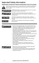
Important Safety Information Explanation of Attention Words and Symbols used in this guide This is the safety alert symbol. It is used to alert you to potential personal injury hazards. Obey all safety messages that follow this symbol to avoid possible injury or death. WARNING WARNING indicates a hazardous situation which, if not avoided, could result in death or serious injury.
CAUTION This PetSafe® In-Ground Fence™ is not a solid barrier. This system is designed to act as a deterrent to remind pets by Static Correction to remain in the boundary established. It is important that you reinforce training with your pet on a regular basis. Proper fit of the collar is important. A collar worn for too long or made too tight on the pet’s neck may cause skin damage. Ranging from redness to pressure ulcers; this condition is commonly known as bed sores.
NOTICE 4 • Plug the Surge Protector into a grounded (3-prong) outlet that is within 5 feet of the Fence Transmitter. ALWAYS use a grounded (3-prong) outlet to ensure maximum protection. • Do not remove the ground prong from the Surge Protector plug. Do not use a 3-prong plug to 2-prong outlet converter. Doing so will make the Surge Protector ineffective against surges or spikes. • Use care when mowing or trimming your grass not to cut the loop wire.
Thank you for choosing PetSafe® brand. You and your pet deserve a companionship that includes memorable moments and a shared understanding together. Our products and training tools promote a lifestyle of protection, teaching, and love — essentials that influence memories for a lifetime. If you have any questions about our products or training your pet, please visit our website at www.petsafe.net or contact our Customer Care Center at 1-800-732-2677.
Troubleshooting............................................................................... 30 Additional Information ....................................................................... 31 System Test ........................................................................................ 32 Transmitter Loop Test (USA and Canada) .......................................... 33 Transmitter Loop Test (Australia and New Zealand) ............................ 33 Wire Break Location Test ....................
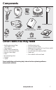
Components Mounting Bracket Boundary Wire - 500 ft. Fence Transmitter Power Adapter Boundary Flags - 50 Receiver Collar Surge Protector (USA and Canada only) Wire Nuts Littl e DPetSaf og In e ® Op Del era -Gro ting ux Plea and se read und e Train this Fenc enti ing re guid e™ Gu e befo ide Mod PIG el Num 00-1 ber 0773 Test Light Tool Gel-filled Capsules Battery (PetSafe® RFA-188) re begi nnin g.
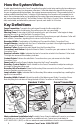
How the System Works A radio signal travels from the Fence Transmitter through a buried wire, marking the boundaries you wish to set for your dog.Your dog wears a Receiver Collar that detects the signal at the boundary. As your dog approaches the boundary, the receiver issues a warning tone. If he proceeds further, he receives a safe but startling Static Correction. While harmless, the correction will persuade him to stay in the containment area you’ve established.
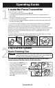
Operating Guide Step Locate the Fence Transmitter 1 Place the Fence Transmitter: • In a dry, well ventilated, protected area (1A, 1B). • In an area where temperatures do not fall below freezing (e.g., garage, basement, shed, closet). • Secured to a stationary surface using the mounting hardware. A mounting template is included on the back of this guide • At least 3 feet from large metal objects or appliances as these items may interfere with the signal consistency (1C).
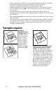
• Design a layout that is suitable for your yard. Sample layouts are provided in this section, and a grid for designing your layout is provided in the back of this guide. • Fence planning software is available online at www.petsafe.net/fence. • Always use gradual turns at the corners with a minimum of 3 foot radius to produce a more consistent boundary (2B). Do not use sharp turns, as this will cause gaps in your boundary.
Double Loop A Double Loop must be used when you are not establishing the Boundary Zone on all sides of your property. When using a Double Loop, the Boundary Wire must be separated by a minimum of 5 FEET to avoid canceling the signal. Remember that a Double Loop will require twice as much wire.
Step Position the Boundary Wire Running the Boundary Wire parallel to and within 10 feet of electrical wires, neighboring containment systems, telephone wires, television or antenna cables, or satellite dishes may cause an inconsistent signal. If you must cross any of these, do so at 90-degree angles (perpendicularly) (3A).
To Splice or Repair the Boundary Wire If you need additional Boundary Wire to expand your wire loop, you will need to splice the wires together. Note the locations of all splices for future reference. 3D 3/8" 3/8" Strip approximately 3⁄8 inch of insulation off the ends of the Boundary Wires to be spliced (3D). Make sure the copper Boundary Wire is not corroded. If the Boundary Wire is corroded, cut it back to expose clean copper wire.
Step Connect the Wires to the Surge 4 Protector and Fence Transmitter (USA and Canada) Surge Protection Lightning strikes that occur even several miles away from your installation can create power surges or spikes which may damage your unprotected electronic pet containment system. The Surge Protector included with this system is designed to protect your In-Ground Fence™ from surges or spikes that can reach it via your AC power connection and/or your buried Boundary Wire.
1. 2. 3. 4. Turn the power OFF to the 4A Fence Transmitter outlet that the Surge Protector and Fence Transmitter will be Loop Power plugged into. Transmitter Adapter We recommend that, if Power Boundary Wire LP-4100 possible, use the outlet center Jack Terminals screw that holds the cover Red Loop Tabs plate in place to secure the Black Transmitter Boundary Wires Surge Protector to the outlet.
Connect the Wires to the Fence Transmitter (Australia & New Zealand) Ground Wire (4C) Proper grounding, although not necessary for the system to work, will help reduce the chance of electrical surges causing damage to your Fence Transmitter and/or Power Adapter. To ground your unit, you will need a stranded 10 gauge insulated copper wire and a UL approved grounding clamp to connect the wire to the grounding rod located at your electrical power service entrance.
Step Prepare the Receiver Collar 5 To Insert and Remove the Battery 5A 5B 5C 5D Note: Do not install the battery while the Receiver Collar is on your pet. This Receiver Collar utilizes a replaceable PetSafe® battery (RFA-188). This unique battery is designed to make battery replacement easier and increase water protection. To activate the collar, insert the battery module (5A).
The Static Correction Levels increase from 1 to 5. Pushing the Correction Level Button while the Receiver Collar is on level 5 will cause the Receiver Collar to revert to level 1. Refer to the Function and Response Table to choose the Static Correction level that best fits your pet. The Receiver Indicator Light acts as a low battery indicator, flashing every 20 seconds when battery replacement is required.
Step Set the Boundary Width and Test the 6 Receiver Collar With the Boundary Wire in place and properly connected, it 6A is time to set the containment field and test the system. CAUTION The Receiver Collar should NOT be on your dog when the system is tested. Note:The Receiver Collar is waterproof, which can make the tone hard to hear. The flashing Test Light when held to the Contact Points indicates the Receiver Collar is delivering Static Correction.
Two seconds after the warning tone, the test light will begin to flash. This flashing light can aid you in identifying the Boundary Width should you have difficulty hearing the tone. To avoid having the Receiver Collar go into Over Correction Protection mode, walk back into the Pet Area until the beeping stops. If the Receiver Collar does not beep at the desired range, adjust 6F the Boundary Width Control knob to obtain the desired range.
Step Install the Boundary Wire 7 NOTICE Before you begin installing the Boundary Wire, unplug the Fence Transmitter power adapter from the Surge Protector or outlet. To Bury the Boundary Wire Burying the Boundary Wire is recommended to protect it and prevent disabling the system. 1. Cut a trench 1-3 inches deep along your planned boundary. 2. Place the Boundary Wire into the trench maintaining some slack to allow it to expand and contract with temperature variations. 3.
To Cross Hard Surfaces (driveways, sidewalks, etc.) WARNING Follow all safety instructions for your power tools. Be sure to always wear your safety goggles. • Concrete Driveway or 7C 7D Sidewalk (7C): Place the Boundary Wire in a convenient expansion joint or create a groove using a circular saw and masonry blade. Place the Boundary Wire in the groove and cover with an appropriate waterproofing compound. For best results, brush away dirt or other debris before patching.
Step Fit the Receiver Collar 9 Important: The proper fit and placement of your Receiver Collar is important for effective training. The Contact Points must have direct contact with your pet’s skin on the underside of his neck. CAUTION Please read and follow the instructions in this manual. Proper fit of the collar is important. A collar worn for too long or made too tight on the pet’s neck may cause skin damage. Ranging from redness to pressure ulcers; this condition is commonly known as bed sores.
4. The Receiver Collar should fit snugly, yet loose 9B enough to allow one finger to fit between a contact point and your pet’s neck (9B). Allow your pet to wear the collar for several minutes, then re-check the fit. Check the fit again as your pet becomes more comfortable with the Receiver Collar. 5. Once you are satisfied with the fit of the Receiver Collar then you may trim any excess collar strap as follows (9C): a. Mark the desired length of the Receiver 9C Collar with a pen.
Training Guide Be Patient With Your Pet Important: Proper training of your pet is essential to the success of the PetSafe® Deluxe Little Dog In-Ground Fence™. Read this section completely before beginning to train your pet. Remember that the PetSafe® Deluxe Little Dog In-Ground Fence™ is not a solid barrier. • Have fun with your pet throughout the training process. Training should be fun, fair, firm and consistent. • Train for 10 to 15 minutes at a time. Don’t try to do too much too quickly.
Steps: 1. Begin by walking your pet on a leash in the Pet Area. Calmly praise and talk to your pet. 2. Move toward the Boundary Flags (10A). Keep your mood happy. 3. With full control of your pet on a leash, walk to the flags. As your pet enters the Static Correction Zone, the Receiver Collar will begin to beep (10B). Allow your pet to stay in the Static Correction Zone for up to 2 seconds then gently help him back into the Pet Area (10C).
Phase Days 5 thru 8 - Distraction Phase 3 Perform three training sessions per day, each lasting 10 to 15 minutes. Goal: To train your pet to stay within the Pet Area with distractions outside of the Pet Area. Setup: • Program the Static Correction Level on the Receiver Collar to level 2 or higher depending on the reaction results from days 2 thru 4. • Put a separate non-metallic collar on your pet’s neck ABOVE the Receiver Collar and attach a leash.
Phase Days 9 thru 14 - Unleashed 4 Supervision Training sessions should start at 10-15 minutes, gradually increasing to over an hour. Your pet is ready for this step only when he clearly avoids the entire Static Correction Zone, regardless of any distractions or temptations. During this step, do not leave your pet unattended. Goal: To give your pet free run of the Pet Area off the leash. Setup: Adjust the Receiver Collar to the permanent setting appropriate for your pet. Steps: 1.
Accessories To purchase additional accessories for your PetSafe® Deluxe Little Dog In-Ground Fence™, contact the Customer Care Center at 1-800-732-2677 or visit our website at www.petsafe.net to locate a retailer near you.
Troubleshooting Receiver Collar is not beeping or correcting. • Check battery to make sure it is installed properly and turned to the ON position. • Perform Static Correction and Battery Test (page 17). If Battery Status LED does not flash Green, replace the battery. • Check that both lights are lit on the Fence Transmitter. If not, perform the “Transmitter Loop Test” (page 33). The Receiver Collar is beeping, but the pet is not responding to the Static Correction.
The Power and Loop Indicator Lights are off. • Check that the Power Adapter is plugged into the Fence Transmitter. • Check that the Power Adapter and/or Surge Protector are plugged in properly. • If the system is plugged into a GFCI or RCD outlet, check to see if the circuit has been tripped. Reset the GFCI or RCD circuit if required. • Verify that the outlet is working properly by plugging in a known working item such as a radio.
System Test The system test is used to determine the cause of system problems that have not been addressed elsewhere in this guide. You will need a 10 foot piece of Boundary Wire with 3⁄8 inch of insulation removed from each end to use as a test loop wire. Follow the steps below to perform the system test: 1. Remove the Receiver Collar from you dog and make sure it is turned on with a good battery installed. 2. Unplug the Power Adapter from the Fence Transmitter Power Jack. 3.
Transmitter Loop Test (USA and Canada) The Transmitter Loop Test is a simple test to determine the cause of a “Boundary Wire Broken or Disconnected” alarm indication. You will need a short 10 foot piece of Boundary Wire with 3⁄8 inch of insulation stripped from both ends. CAUTION The receiver collar should not be on your dog when the system is tested. Your pet may receive an unintended correction.
Wire Break Location Test Please follow these steps in determining where you have a break in your Boundary Wire: 1. Locate your original splice(s) and verify they have a good, solid connection. 2. Check your yard to determine any possible damage to the Boundary Wire (e.g. recent digging, aerating, rodent burrowing, or any other noticeable disturbance in your yard next to the Boundary Wire).
Compliance FCC/Canada This Class B digital apparatus complies with Canadian ICES-003. This equipment has been tested and found to comply with the limits for a Class B digital device, pursuant to Part 15 of the FCC Rules. These limits are designed to provide reasonable protection against harmful interference when the equipment is operated in a residential environment.
Layout Grid Mounting Template 3.000" (7.62 cm) Radio Systems® Corporation 10427 Electric Avenue Knoxville, TN 37932 1-800-732-2677 www.petsafe.net Protected by US Patents 6,921,089, 7,541,937, and D531,117. Other patents pending.